 |
|||
|
|
|||
|
|
|||
| ||||||||||
|
|
 TM 5-2410-233-23
TRACK ASSEMBLY REPLACEMENT - CONTINUED
0119 00
REMOVAL - CONTINUED
NOTE
Steel slug must have contact with track bushing when sprocket is turned in reverse.
Position drawbar pin evenly on sprocket.
4.
Install drawbar pin (4) between teeth of sprocket (5).
WARNING
Keep all personnel clear of front and rear
of machine. If track separation occurs,
track movement is fast and uncontrolled.
At least 20 ft (6 m) of clearance is required
in front and rear of machine. Failure to
follow this warning may result in injury or
death to personnel.
386-251
4
5
5.
Start machine (TM 5-3410-233-10).
6.
Move machine to the rear, until drawbar pin (4) is in 9
o'clock position (3 o'clock position for left-hand
track), to put tension to the rear against force of recoil
spring and push grease out of vent holes.
7.
Move machine forward to release tension on track.
8.
Remove drawbar pin (4) from teeth of sprocket (5).
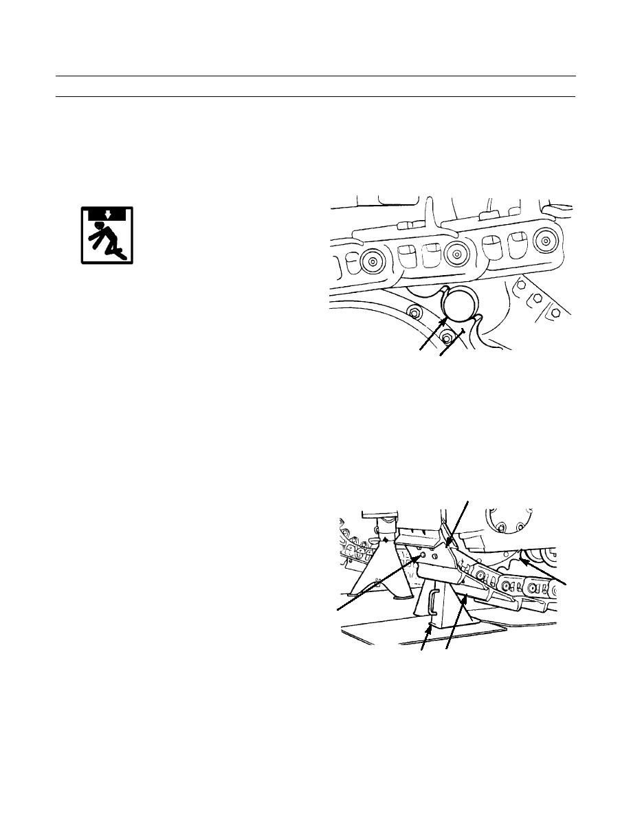
9.
Move machine until master link (6) is in 8 o'clock position (4 o'clock position for left-hand track) on sprocket (6).
10.
Install track block (7) under track shoe (8) next to
6
master link (6) and move track until track shoe makes
contact with track block.
5
9
386-252
8
7
0119 00-2
|
|
Privacy Statement - Press Release - Copyright Information. - Contact Us |
