 |
|||
|
|
|||
|
|
|||
| ||||||||||
|
|
 TM 5-2410-233-23
FINAL DRIVE BEARINGS ADJUSTMENT - CONTINUED
0104 00
ADJUSTMENT - CONTINUED
NOTE
If necessary, tighten adjusting nut to install lock
in one adjusting nut.
12.
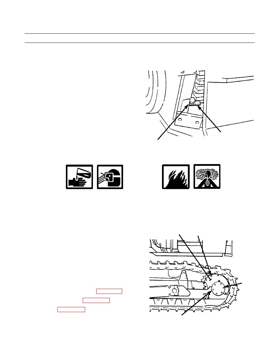
Install lock (10) with capscrew (8) and nut (9).
10
386-564
8,9
13.
Remove the following tools: capscrews, washers,
bearing adjusting tool and stand.
WARNING
Exposure to silicone RTV compound may be hazardous to your health. Contact with eyes can cause severe
irritation and burns. Compound can be absorbed into the skin and can cause irritation or skin sensitiza-
tion. Inhalation of vapors can cause respiratory tract irritation; prolonged inhalation can result in an aller-
gic reaction. Vapors are combustible. Do not use near open flame. Wear eye and skin protection and avoid
inhalation of vapors. Use only in a well-ventilated area. Failure to follow this warning can cause injury or
death.
NOTE
3
1,2
Coat both sides of new gasket (7) with silicone
RTV compound.
14.
Position new gasket (7) and cap (6) and install six
bolts (4) and new lockwashers (5).
15.
Install guard (3) with six bolts (1) and new lockwash-
ers (2).
4,5
16.
Lubricate track roller frame outer bearings by filling
retainer cavity with GAA grease (WP 0009 00).
17.
Lower machine to ground (WP 0178 00).
18.
Adjust track (WP 0120 00).
386-563
6,7
END OF WORK PACKAGE
0104 00-5
|
|
Privacy Statement - Press Release - Copyright Information. - Contact Us |