 |
|||
|
|
|||
|
|
|||
| ||||||||||
|
|
 TM 5-2410-233-23
BEVEL GEAR AND SHAFT REPLACEMENT - CONTINUED
0102 00
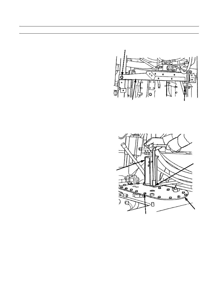
REMOVAL
1.
Remove capscrew (1) and washer (2) from end of sup-
1,2
port assembly (3) at gear case.
2.
Remove two capscrews (4), nuts (5) and lockwashers
(6) from other end of support assembly (3) and
remove support assembly. Discard lockwashers.
386-548
3
4,5,6
3.
Remove four capscrews (7), lockwashers (8) and bracket assembly (9) from top of gear case cover (10). Discard lock-
washers.
4.
Remove 19 capscrews (11), washers (12), three spac-
ers (13) and cover (10) from bevel gear case.
5.
Remove oil lines from two bearing cages (14 and 15).
6.
Use a piece of bar stock between teeth in bevel gear
(16) and bottom of gear case to hold gear while
removing 10 nuts (17) and washers (18).
NOTE
7,8
Weight of bevel gear shaft is 46 lb (21 kg).
7.
Attach a nylon sling and a suitable lifting device to
9
bevel gear shaft (19) for support.
8.
Remove eight capscrews (20) and lockwashers (21)
from bearing cage (14) at bevel gear end of bevel gear
shaft (19). Discard lockwashers.
9.
Install two 1/2 in. -13NC forcing screws in bearing
cage (14) and turn screws evenly to remove cage.
Remove forcing screws from bearing cage.
10
11, 12, 13
386-549
0102 00-2
|
|
Privacy Statement - Press Release - Copyright Information. - Contact Us |
