 |
|||
|
|
|||
|
|
|||
| ||||||||||
|
|
 TM 5-2410-233-23
BEVEL GEAR AND SHAFT REPLACEMENT - CONTINUED
0102 00
REMOVAL - CONTINUED
NOTE
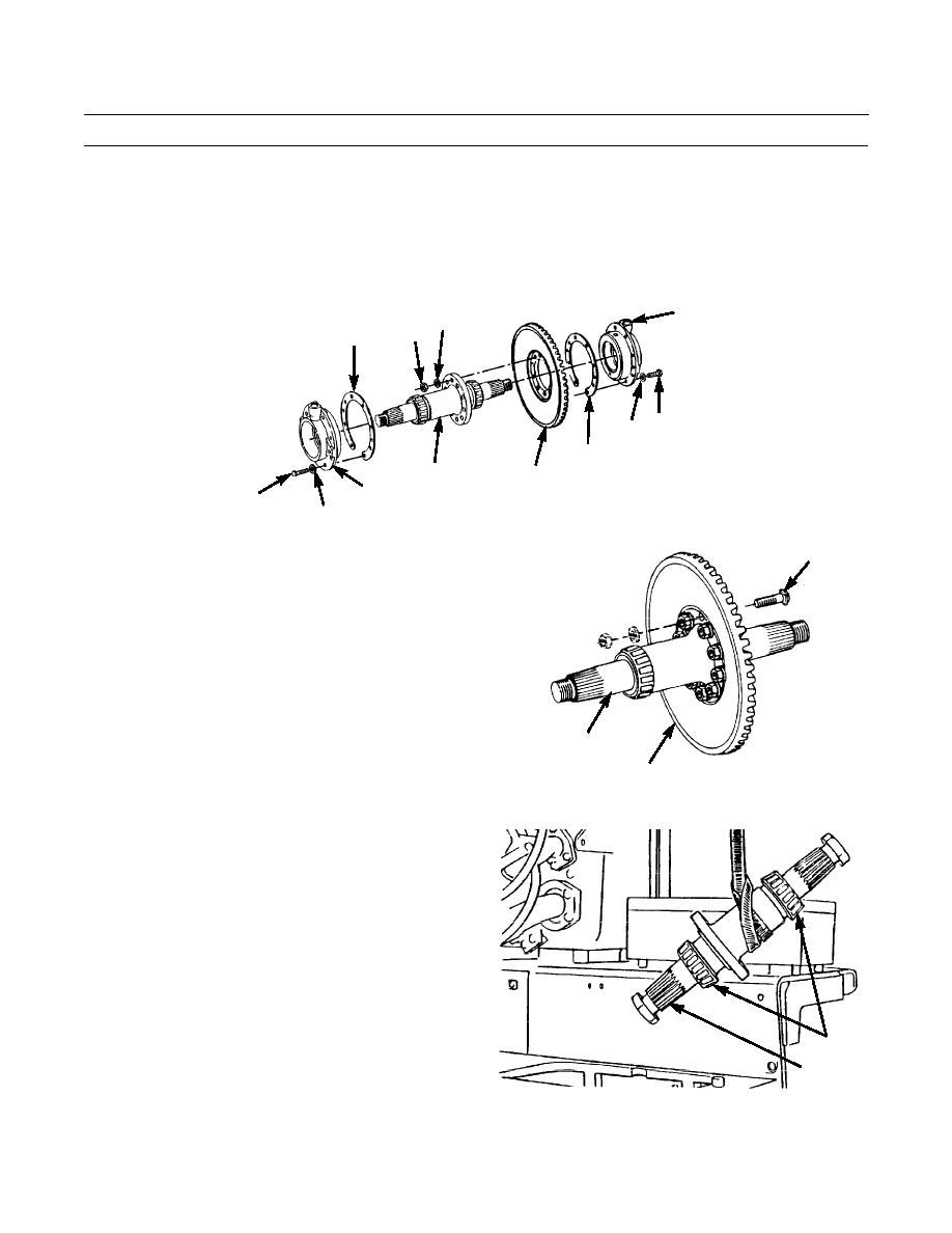
Keep shims together for each bearing cage for installation purposes.
10.
Remove shims (22) from bearing cage (14).
11.
Repeat steps 8 through 10 for bearing cage (15) at steering clutch end of bevel gear shaft (19).
14
18
17
22
20
21
22
19
16
386-550
15
20
21
CAUTION
23
Install large nut on each end of bevel gear shaft
to protect threads from damage.
12.
Slide bevel gear shaft (19) 3/4 in. toward clutch com-
partment and remove 10 capscrews (23) from bevel
gear (16).
19
386-551
16
NOTE
Put wood block under bevel gear during
removal of gear shaft.
13.
Use lifting device to slowly remove bevel gear shaft
(19) through steering clutch compartment.
14.
Remove large nut from each end of bevel gear shaft
(19). Use a puller to remove two bearings (24).
24
19
386-552
0102 00-3
|
|
Privacy Statement - Press Release - Copyright Information. - Contact Us |