 |
|||
|
|
|||
|
|
|||
| ||||||||||
|
|
 TM 5-2410-233-23
0100 00
REMOVAL - CONTINUED
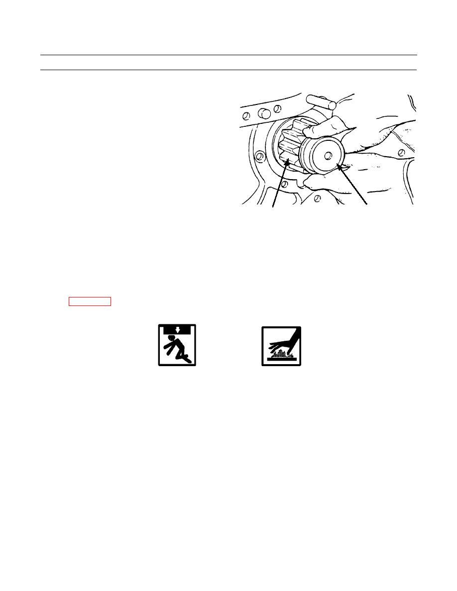
30.
If necessary, pull bearing race (30) from pinion shaft
(31).
30
31
386-540
CLEANING
1.
Wipe clean and dry all bearing mounting surfaces in openings and on shafts.
2.
Wipe all gears clean.
3.
Clean all gasket sealing surfaces before installation of new gasket compound.
INSPECTION
See WP 0176 00 for general inspection instructions.
INSTALLATION
WARNING
Use extreme caution when handling heavy parts. Provide adequate support and use assistance
during procedure. Ensure that any lifting device used is in good condition and of suitable load
capacity. Keep clear of heavy parts supported only by lifting device. Failure to follow this
warning may cause injury or death.
Wear hand protection when handling both hot and cold components to prevent injury.
NOTE
This procedure applies to either R.H. or L.H. final drive assembly.
1.
Heat bearing race (30) evenly to a maximum temperature of 275F (135C). Install bearing race on pinion shaft (31).
2.
Lower temperature of race and roller assembly (29). Align hole in race and roller assembly with hole in bearing cage
(27) and install race and roller assembly in cage.
3.
Use a 1/4 in. -20NC capscrew to install dowel (28) in bearing cage (27). Remove capscrew.
4.
Apply gasket compound on contact surfaces of bearing cage (27) and steering clutch case (6). Install bearing cage in
steering clutch case with oil groove next to race and roller assembly (29) at bottom of hole.
5.
Install four new locks (25) and eight capscrews (26) to secure bearing cage (27) to steering clutch case (6). Bend locks
up against flats of capscrew heads.
0100 00-7
|
|
Privacy Statement - Press Release - Copyright Information. - Contact Us |
