 |
|||
|
|
|||
|
|
|||
| ||||||||||
|
|
 TM 5-2410-233-23
0100 00
REMOVAL - CONTINUED
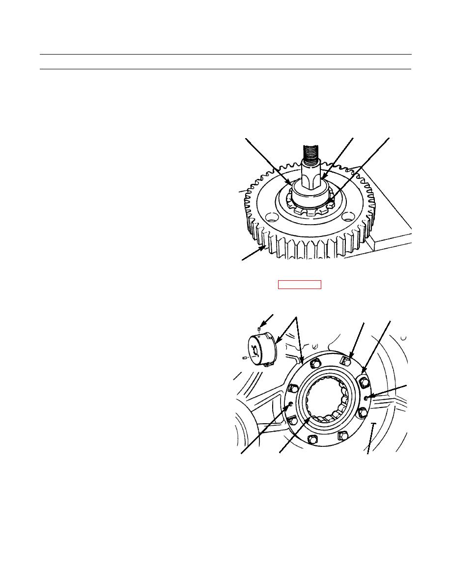
NOTE
Weight of idler pinion is 85 lb (39 kg).
23.
Push retainer (23) in groove on shaft of idler pinion
20
23
24
(20). Retainer will stay in groove because of pressure
on idler pinion shaft. When retainer is completely in
groove, idler pinion shaft will slide out of gear (21).
Discard retainer.
24.
Pull bearing race (24) from other end of idler pinion
(20) shaft.
386-538
21
25.
Drain oil from bevel gear case and applicable steering clutch compartment (WP 0086 00).
26.
Bend four locks (25) down. Remove eight capscrews (26) and four locks from bearing cage (27). Discard locks.
27.
Install two 1/2 in. -13NC forcing screws in bearing
28
27
25
cage (27) at tapped holes (B). Tighten forcing screws
26
evenly and remove bearing cage from steering clutch
case (6). Remove forcing screws from bearing cage.
NOTE
Dowel is located behind flange of bearing cage.
28.
Use a 1/4 in. -20NC capscrew to remove dowel (28)
B
from bearing cage (27). Remove capscrew from dow-
els.
29.
Pull race and roller assembly (29) from bearing cage
(27).
B
386-539
29
6
0100 00-6
|
|
Privacy Statement - Press Release - Copyright Information. - Contact Us |
