 |
|||
|
|
|||
|
Page Title:
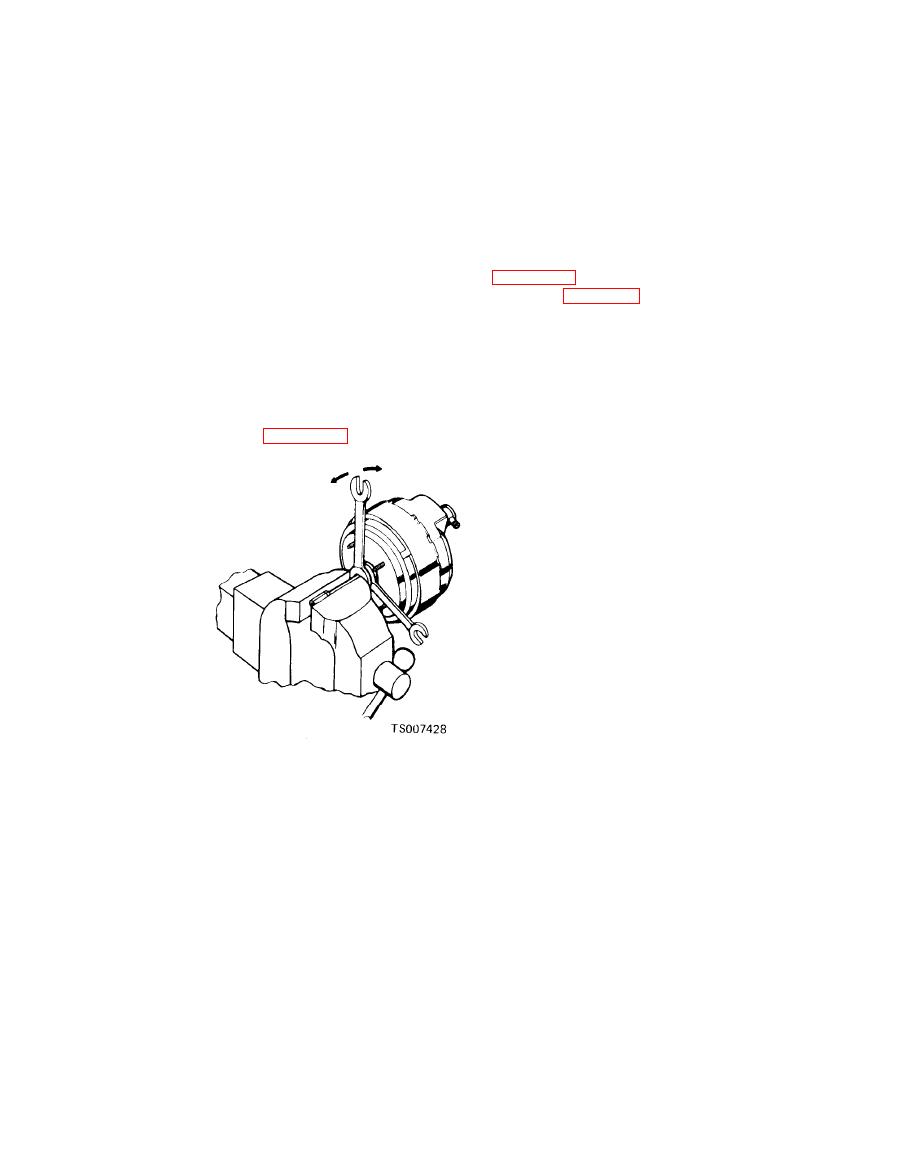
Figure 9-7. Removing Value Rod. |
|
||
| ||||||||||
|
|
 TM 10-3930-633-34
CAUTION
NOTE
Do not disturb adjustment screw on end of hydraulic
When separating valve rod from
pushrod.
plunger, hold power section to prevent it
(2) Remove hydraulic pushrod from front
from falling to the floor.
shell of power section and then remove front
(4) Use care when prying with wrenches to
vacuum seal from pushrod. Wet valve rod eye and
avoid damage to plastic valve hub. Remove valve
small diameter of dust guard with alcohol and
rod from vise. Carefully pry retainer off end of
then remove dust guard from valve rod and hub of
valve hub. Do not chip or crack plastic. Remove
rear shell. Pull vacuum check valve straight out
valve return spring, poppet retainer and poppet.
of grommet in front shell.
(5) Make up a removal tool as shown in
(3) Remove air filter-silencers from valve
hub. With operating rod in vertical position,
shown in figure 9-8, and insert rear shell studs in
squirt alcohol down rod to wet rubber grommet in
matching holes in base (three or four studs as
valve plunger at ball end of valve rod. Clamp
required). Place flat bar wrench over studs of
valve in soft-jawed vise. Leave just enough space
front shell and align top clamp bar with base.
between steel retainer on plastic valve hub and
Attach hook bolts of top clamp bar to holes at
side of vise jaw for two medium sized open end
opposite ends of base. Tighten T-handle center
wrenches. Use wrench nearest vise as a pry to
bolt just enough to compress shells and free
force valve plunger (and power section) off ball
twelve lanced locks around shell edges. Turn flat
end of valve rod. See figure 9-7.
bar wrench counterclockwise until cut-outs on
front shell are aligned with locks on rear shell.
Unscrew center bolt. Shells should begin to
separate as load on center bolt is released. If
shells do not separate, check cut-out and lock
alignment and then tap shell flange lightly with
soft hammer to break bond between diaphragm
and shells.
|
|
Privacy Statement - Press Release - Copyright Information. - Contact Us |