 |
|||
|
|
|||
|
Page Title:
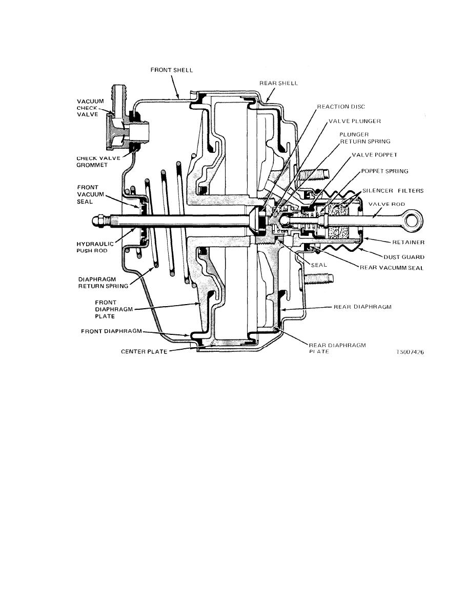
Figure 9-5. Vacuum Power Unit Cross Section |
|
||
| ||||||||||
|
|
 TM 10-3930-633-34
Figure 9-5. Vacuum Power Unit Cross Section
a secondary piston with two "back-to-back"
(2) A manually actuated control valve in-
tegral with the vacuum power diaphragm and
secondary seals, primary cup, protector, spring
plate hubs that controls the degree of power brake
and spring retainer; a piston stop screw and O-
application or release in accordance with the foot
ring seal; and two separate check valves (residual
pressure applied to the valve operating rod
p r e s s u r e ) , springs and tube seat retainers
through the brake pedal linkage. The control
mounted in the two outlet ports provide the
valve consists of a single poppet with an at-
operating components o f the two separate
mospheric port and a vacuum port. The vacuum
hydraulic systems. See TM 10-3930-633-12 for
port seat is formed in the hub of the rear
complete description and repair procedures on the
diaphragm plate. The atmospheric port seat is
master cylinder.
part of the valve plunger which moves within the
c. Operation.
valve housing hub of the diaphragm plates.
(1) The vacuum power diaphragm plates and
parts that make up the valve assembly are
(3) A hydraulic dual-system master cylinder
connected to the brake pedal through the valve
that provides two hydraulic fluid reservoirs, cast
operating rod. The valve operating rod is con-
integrally with and connected to the bore through
nected to the valve plunger which moves within
separate sets of compensating and fluid inlet (by-
the hub of the power diaphragm and plate
pass) ports. Both reservoirs are sealed by a
assembly. A valve return spring returns the valve
rubber diaphragm inside the baletype cover. A
plunger and valve rod to the released position
primary piston assembly with secondary seal,
when the brake pedal is released. The valve
primary cup, protector, spring, screw and spacer;
|
|
Privacy Statement - Press Release - Copyright Information. - Contact Us |