 |
|||
|
|
|||
|
Page Title:
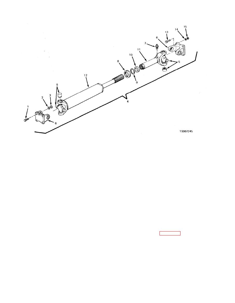
Figure 8-1. Propeller Shaft Assembly. |
|
||
| ||||||||||
|
|
 TM 10-3930-633-34
1.
Screw
6. Flange yoke
11.
Sleeve yoke
2.
Lockwasher
7. Lubrication fitting
12.
Stub yoke
3.
Nut
8. Dust cap
13.
Screw
4.
Shaft assembly
9. Steel washer
14.
Lockwasher
5.
Cross and bearings
10. Cork washer
15.
Nut
(1) Remove snap rings by pinching the ends
(2) Do not disassemble the needle bearings.
together with a pair of needle nose pliers. If a ring
Clean with short stiff brush and blow out with
c o m p r e s s e d air. Work a small quantity of
does not readily free from the groove, tap the end
lubricant (140 S. A. E. oil) into each bearing cap
of the bearing cap lightly to relieve the pressure
and turn the needle bearing on the trunnion to
against the ring.
check wear. Replace if worn.
(2) Remove needle bearings (5) by driving on
(3) Because worn needle bearings used with a
the end of one bearing cap until the opposite
journal cross or new needle bearings used with a
bearing cap is forced out of the yoke. Turn the
worn journal cross will wear more rapidly, making
joint over and tap on the end of the journal cross
another replacement necessary in a short time,
until the opposite bearing cap is free. Use a
always replace the journal cross and four needle
wooden dowel, of a diameter about 1/32 to 1/16
bearing caps as a unit. These parts are furnished
smaller than the hole in the yoke, as a drift.
together in the service assembly. (See TM 10-
(3) Separate journal cross and yokes by
3930-633-34P).
sliding journal to the side of the yoke, and tilting
over the top of the yoke lug.
the propeller shaft as follows:
(4) Free slip yoke (11) and stub yoke (12) by
unscrewing dust cap (8) and pulling apart.
(1) Lubricate the splines on the stub shaft
with clean engine oil (OE) and place dust cap (8),
b. Cleaning, Inspection, and Repair.
(1) Clean all parts in a bath of solvent,
steel washer (9) and cork washer (10) over the
Federal Specification P-D-680. Allow the parts to
stub spline (11).
remain in the solvent for some time to loosen up
(2) Slide stub yoke (12) into slip yoke (11),
any particles of grease or foreign matter, Remove
being very careful to make certain the arrows
stamped on the slip yoke and stub yoke are
any burrs or rough spots from any machined
surf aces.
exactly in line. Tighten dust cap on slip yoke.
|
|
Privacy Statement - Press Release - Copyright Information. - Contact Us |
