 |
|||
|
|
|||
|
|
|||
| ||||||||||
|
|
 TM 10-3930-633-34
(3) Remove the separator plate.
on the transmission case and install the two
(4) Wash all parts thoroughly in clean
attaching bolts. T o r q u e the bolts to 1722
ft/lbs.
solvent and blow dry with moisture-free com-
pressed air.
(2) Check the converter pressure and control
(5) Inspect the regulator body and cover
pressure valves to be sure the valves operate
freely in the bores.
mating surfaces for burrs.
(6) Check all fluid passages for obstructions.
(3) Install the valve springs, spacer and
retainer.
(7) Inspect the control pressure and con-
verter pressure valves and bores for burrs and
(4) Install the main pressure oil tube. Be
sure to install the end of the tube that connects to
scores. Remove all burrs carefully with crocus
the pressure regulator assembly first. Then,
cloth.
install the other end of the tube into the main
(8) Check the free movement of the valves in
control assembly by tapping it gently with a soft
their bores. Each valve should fall freely into its
hammer.
bore when both the valve and bore are dry.
(9) Inspect the valve springs for distortion.
(5) Install the small compensator pressure
tube.
c. Assembly.
(1) Position the separator plate on the
(6) Install the fluid screen and the pan, and
fill the transmission to the correct level with the
regulator cover.
specified fluid.
( 2 ) Position the regulator cover and
separator plate on the regulator body, and install
the attaching screws. Torque the screws to 20
a. Disassembly.
30 in./lbs.
(1) Remove the inner downshift lever shaft
( 3 ) Insert the valves in the pressure
nut (fig. 7-24). Then remove the inner downshift
regulator body (fig. 7-23).
lever.
d. Installation.
(1) Position the replacement regulator body
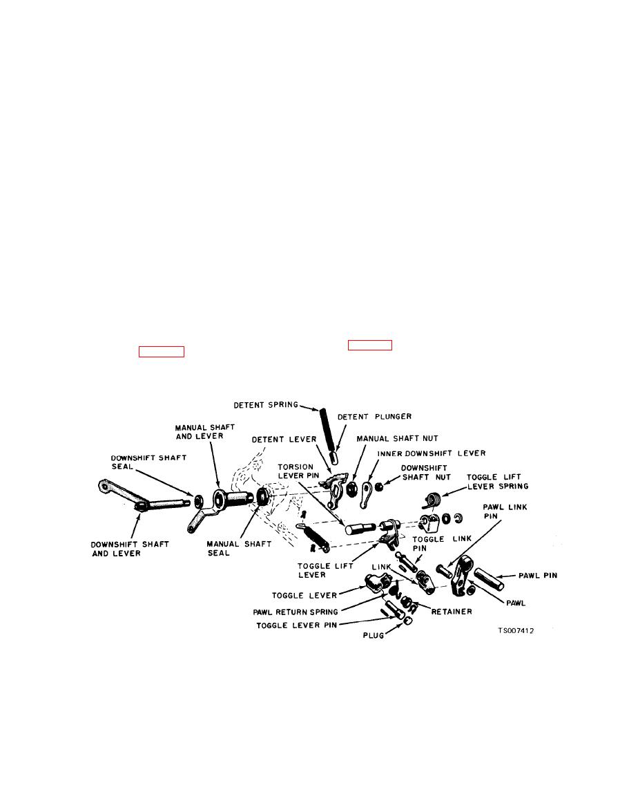
Figure 7-24. Manual Linkage.
(4) Rotate the manual shaft until the detent
(2) Remove the outer downshift lever and
lever clears the detent plunger. Then remove the
shaft. Remove the downshift shaft seal from the
detent plunger and spring. Do not allow the
counterbore in the manual lever shaft.
detent plunger to fly out of the case.
(3) Remove the cotter pin from the parking
(5) Remove the manual lever shaft nut, and
pawl toggle operating rod and remove the clip
remove the detent lever. Remove the outer
from the parking pawl operating lever, Remove
the parking pawl operating rod.
|
|
Privacy Statement - Press Release - Copyright Information. - Contact Us |
