 |
|||
|
|
|||
|
|
|||
| ||||||||||
|
|
 TM 10-3930-633-34
assembly in the bore of the valve body. Install the
(3) Remove the governor valve body from
sleeve, and plug.
the counterweight. Do not drop the attaching
(2) Install the screen.
bolts or the valve parts into the extension
housing.
(3) Install the body on the counterweight.
Make sure the fluid passage in the body and the
b. Disassembly.
counterweight are aligned.
(1) Remove the governor valve body cover.
(4) Position the valve body cover on the
( 2 ) Remove the valve body from the
body, and install the screws.
counterweight.
e. Installation.
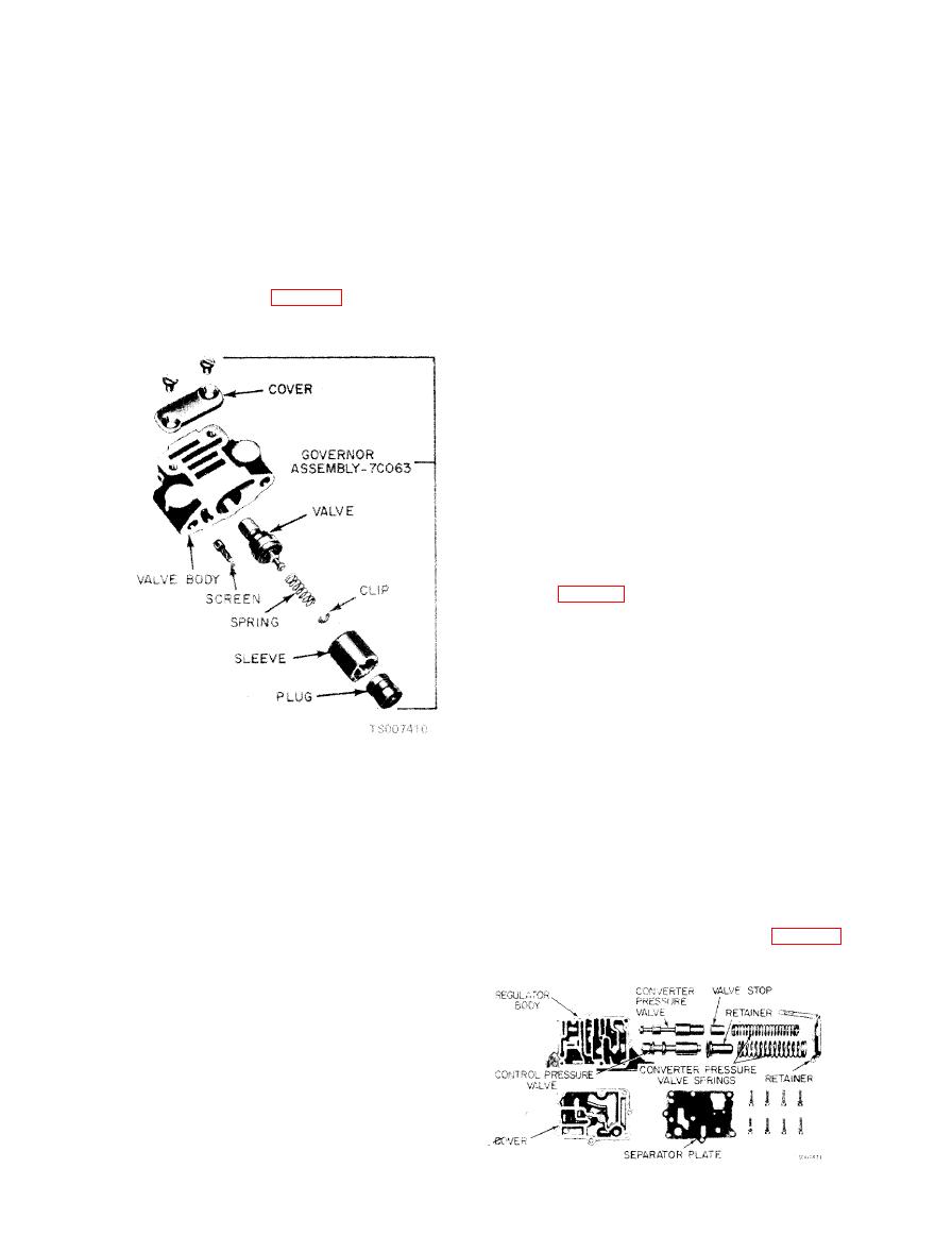
(3) Remove the plug, sleeve, and the valve
(1) Lubricate the new governor valve parts
and spring from the body (fig. 7-22).
with transmission fluid. The valve must move
freely in the valve body bore.
( 2 ) Install the governor body on the
counterweight. so that the valve body cover is
facing rearward. Tighten the two attaching bolts
securely.
(3) Install the governor inspection cover,
using a new gasket.
a. Removal.
(1) Drain the fluid from the transmission,
and remove the pan and fluid screen.
(2) Remove the small compensator pressure
tube from the control valve body and the pressure
regulator (fig. 7-14).
(3) Remove the main pressure oil tube first,
by gently prying up the end that connects to the
main control valve assembly. Then, remove the
other end of the tube from the pressure regulator.
Be sure to remove the tube in this manner.
Failure to do so could kink or bend the tube,
causing excessive transmission internal leakage.
(4) Remove the pressure regulator spring
retainer, springs and spacer. Maintain pressure
(4) Remove the screen from its bore in the
on the retainer to prevent the springs from flying
valve body.
out.
c. Inspection.
(5) Remove the pressure regulator attaching
(1) Inspect the governor valves and bores for
bolts and washers, and remove the regulator.
scores. Minor scores may be removed from the
b. Disassembly and Inspection.
valves with crocus cloth. Replace the governor if
(1) Remove the valves from the regulator
the valves or body is deeply scored.
body.
(2) Inspect the governor screen for ob-
(2) Remove the regulator body cover at-
taching screws and remove the cover (fig. 7-23).
structions. The screen must be clean and free of
foreign material. If it is contaminated, it should
be cleaned in a suitable solvent and thoroughly
blown out with compressed air.
(3) Check for free movement of the valves in
the bores. The valves should slide freely of their
own weight in the bores when dry. Inspect fluid
passages in the valve body and counterweight for
obstructions. All fluid passages must be clean.
(4) Check the mating surface of governor
valve and the counterweight for burrs or scratch-
es.
d. Assembly.
(1) Install the governor valve and spring
|
|
Privacy Statement - Press Release - Copyright Information. - Contact Us |
