 |
|||
|
|
|||
|
Page Title:
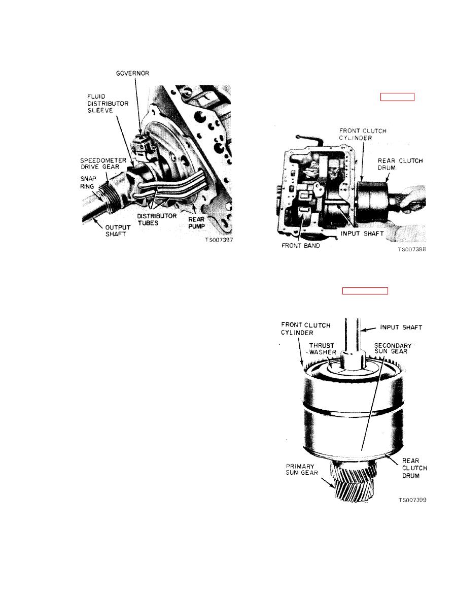
Figure 7-9. Output Shaft and Rear Pump. |
|
||
| ||||||||||
|
|
 TM 10-3930-633-34
(14) Remove the two center support outer
bolts (one each side) from the transmission case.
(15) Exert enough pressure on the end of the
input shaft to hold the clutch units together.
Then remove the center support and the front and
rear clutch assemblies as a unit (fig. 7-10).
(4) Place the output shaft assembly on the
bench and remove the oil distributor tubes from
(16) Set the clutch assemblies up on the sun
the sleeve.
gear end as shown in figure 7-11.
(5) Slide the speedometer drive gear off the
shaft.
(6) If the drive gear ball does not fall out as
the speedometer gear is removed, remove the ball
from the seat in the output shaft.
(7) Remove the distributor sleeve. Remove
the four seal rings from the output shaft with the
fingers to prevent breaking the rings.
(8) Remove the governor snap ring from the
output shaft. Slide the governor assembly off the
output shaft. Then remove the governor drive
ball. Remove the rear pump, extension housing
and pump gaskets.
(9) Remove the rear pump drive key from the
output shaft. Then remove the bronze thrust
washer from the output shaft.
(10) Remove the selective thrust washer
from the rear of the pinion carrier.
(11) Remove the two seal rings from the
primary sun gear shaft. Remove the pinion
carrier.
(12) Remove the primary sun gear rear
thrust bearing and race from the pinion carrier.
(13) Note the rear band position for reference
in assembly. The end of the band next to the
adjusting screw has a depression (dimple) in the
(17) Remove the thrust washer from the
center of the boss. Squeeze the ends of the rear
front of the input shaft.
band together, tilt the band to the rear, and
(18) To remove the front band, position the
remove the rear band from the case.
|
|
Privacy Statement - Press Release - Copyright Information. - Contact Us |