 |
|||
|
|
|||
|
Page Title:
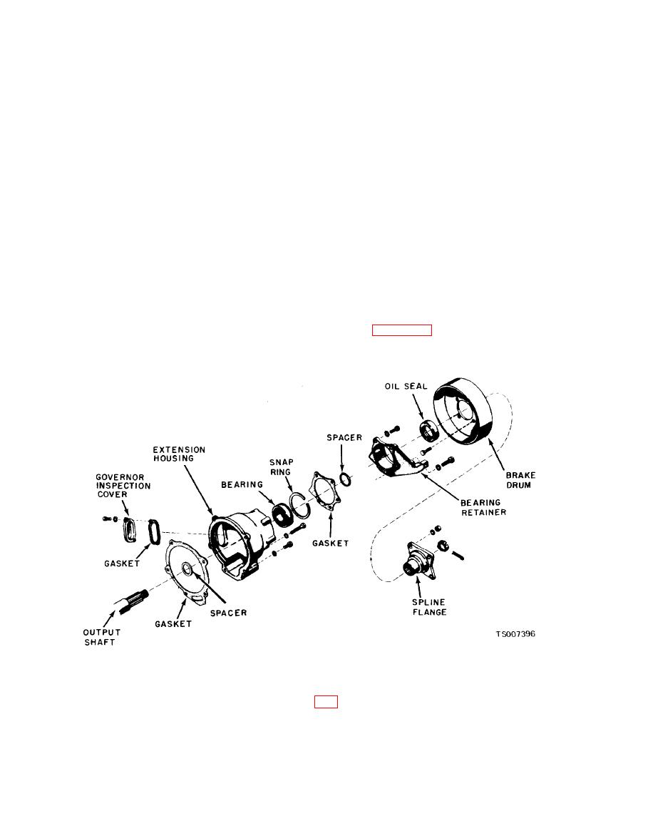
Figure 7-8. Extension Housing Parts. |
|
||
| ||||||||||
|
|
 TM 10-3930-633-34
forward position to eliminate all output shaft end
(11) Remove the regulator from the case,
Keep the control pressure valve and the' converter
play.
pressure regulator valve in the pressure regulator
(4) Move the pinion carrier all the way
forward by inserting a screwdriver between the
to avoid damage to the valves.
planet carrier and the large internal gear and
(12) Remove the front servo, apply and
release tubes by twisting and pulling at the same
prying against the case. Maintain slight forward
time. Remove the front servo attaching bolts.
pressure, and set the dial indicator at zero.
Hold the front servo strut with the fingers, and
(5) Measure and record the end play between
the front of the case and the large internal gear by
lift the servo assembly from the case.
prying between the front clutch cylinder and the
(13) Remove the rear servo attaching bolts.
case. This end play should be 0.010-0.029 inch.
Hold the actuating and anchor struts with the
Total end play including output shaft end play
fingers, and lift the servo from the case.
must not exceed 0.044 inch.
b. Transmission End Play Check.
c. Removal of Case and Extension Housing
(1) Remove one of the front pump attaching
bolts. Mount a dial indicator support in the front
Parts.
pump bolt hole. Mount a dial indicator on the
(1) Remove the remaining front pump at-
taching bolts. Then remove the front pump and
support so that the contact rests on the end of the
turbine shaft.
gasket. (If necessary, tap the screw bosses with a
soft-faced hammer to loosen the pump from the
(2) pry the output shaft all the way forward
by using a screwdriver between the large internal
case.) Remove the parking brake drum and spline
flange. See figure 7-8.
gear and the case.
(3) Lightly block the output shaft in the
(2) Remove the extension housing seal.
(3) Remove the output shaft assembly (fig.
Remove the lubrication tube from the case.
between the distributor sleeve and case as the
R e m o v e the five transmission to extension
housing bolts. These bolts also attach the rear
tubes are removed from the case.
support to the case. Remove the extension
housing.
|
|
Privacy Statement - Press Release - Copyright Information. - Contact Us |
