 |
|||
|
|
|||
|
Page Title:
Section II. ADJUSTMENTS AND TESTS |
|
||
| ||||||||||
|
|
 TM 10-3930-633-34
through the oil cooler, then the cooled fluid is
j. Reverse. When the manual valve is shifted
used in the transmission lubricating circuit.
into reverse, control pressure is directed to apply
(2) A spring-loaded check valve is used in the
the rear clutch and rear band. Governor supply
circuit to maintain about 3-5 PSI in the converter
pressure is cut off by the manual valve; hence, the
out circuit. When the converter out circuit ex-
transmission cannot shift automatically. Rear
ceeds 3-5 PSI, the check ball opens against spring
clutch pressure is also directed to the throttle
pressure and cooled fluid is directed to lubricate
valve to regular throttle pressure to obtain the
the various parts of the transmission gear train.
correct line pressure for the reverse circuit.
k. Fluid Cooling and Lubricating System.
(1) The converter out circuit is directed
Section Il. ADJUSTMENTS AND TESTS
7-4. General
Prior to removal of the transmission from the
vehicle for disassembly or repair, make certain
that a band adjustment as outlined below is not
the cause of malfunction. The tests outlined in the
following paragraphs will aid in determining the
exact cause of the malfunction.
7-5. Band Adjustments
a. Front Band Adjustment.
(1) Drain the fluid from the transmission. If
the same fluid is to be used again in the trans-
mission after the band adjustment, filter the
fluid through a 100-mesh screen as it drains
from the transmission. Reuse the fluid only if it is
in good condition.
(2) Remove the pan, then remove the fluid
filter and clip from the transmission. Clean the
inside of the pan. Remove all gasket material
from the pan and pan mounting face of the case.
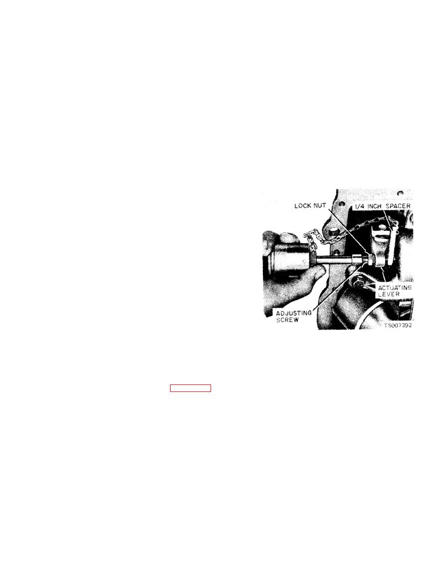
(3) Loosen the front servo adjusting screw
(4) Pull the adjusting screw end of the ac-
lockut two full turns with a 9/16 inch wrench.
tuating lever away from the servo body, and
Check the adjusting screw for free rotation in the
insert the inch spacer between the servo piston
actuating lever after the locknut is loosened, and
stem and the adjusting screw.
free the screw if necessary. See figure 7-3.
|
|
Privacy Statement - Press Release - Copyright Information. - Contact Us |
