 |
|||
|
|
|||
|
Page Title:
Table 6-8. Oil Pump Specifications |
|
||
| ||||||||||
|
|
 TM 10-3930-633-34
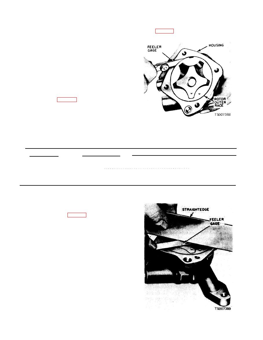
(4) Measure the outer race to housing
Remove the inner rotor "and shaft
(2)
clearance (fig. 6-59).
assembly, then remove the outer race.
(3) Scrape away the staking marks on the
body around the oil pressure relief valve cap. Drill
a 1/8-inch hole in the relief valve cap and insert a
self-threading s h e e t metal screw of proper
diameter into the cap. Pull the cap out of the
chamber. Remove the spring and plunger.
b. Cleaning. Wash all parts in a solvent and dry
them thoroughly with compressed air. Use a
brush to clean the inside of the pump housing and
the pressure relief valve chamber. Be sure all dirt
and metal particles are removed.
c. Inspection.
(1) Refer to table 6-8 for clearances and wear
limits.
(2) Check the inside of the pump housing and
the outer race and rotor for damage or excessive
wear or scoring.
(3) Check the mating surface of the pump
cover for wear. If the cover mating surface is
worn, scored or grooved, replace the cover.
SPECIFICATION
ITEM
.
--
.
. .20.6-22.6 lb
Relief
valve
spring
tension
.
.
at 2.490 length
Drive shaft-to-housing clearance
0.0015-0.0029 in.
Relief
valve
clearance
.
.
.
.
0.0015-0.0029in
Rotor
end
play
.
.
.
.
.
.
.
.
.
.
.
.
.
.
...0.0010-0.00409.
Outer race-to-housing clearance . . . . . . . .
0.001-0.013 in.
(5) With the rotor assembly installed in the
housing, place a straightedge over the rotor
assembly and the housing. Measure the clearance
(rotor end play) between the straightedge and the
rotor and outer race (fig. 6-60). The outer race,
shaft and rotor are replaceable only as an
assembly.
|
|
Privacy Statement - Press Release - Copyright Information. - Contact Us |