 |
|||
|
|
|||
|
|
|||
| ||||||||||
|
|
 TM 10-3930-633-34
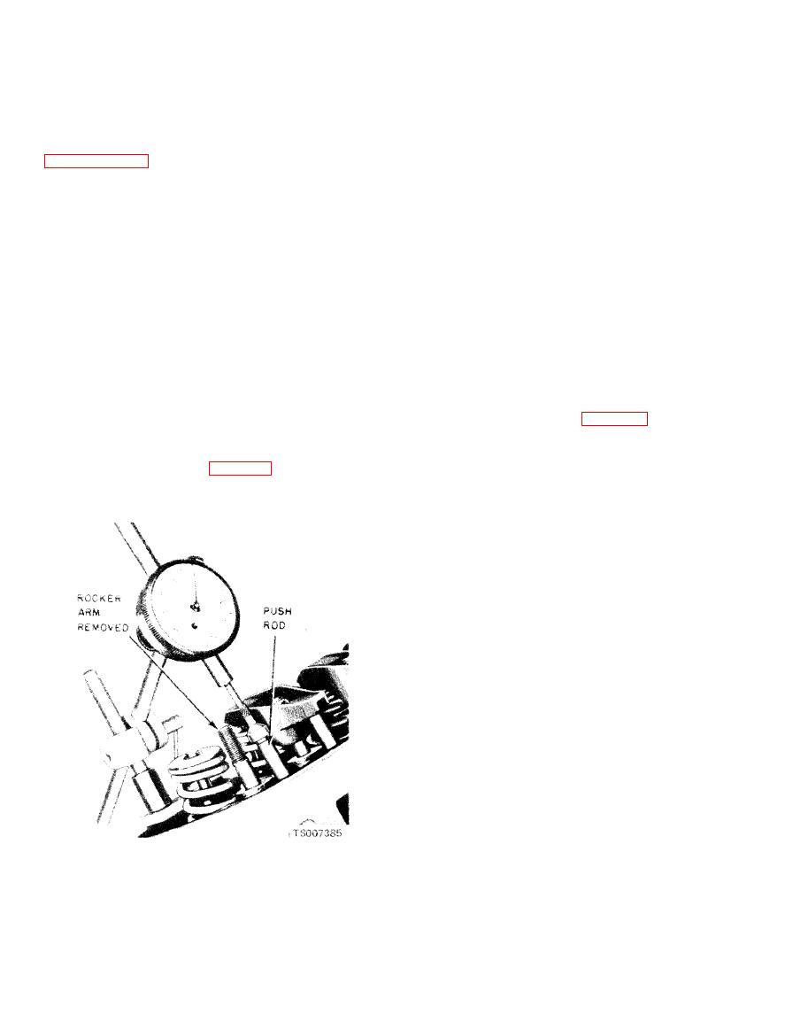
(2) Make sure the pushrod is in the valve
unless the camshaft lobe lift loss has exceeded
lifter socket. Install a dial indicator so that the
0.005 inch.
actuating point of the indicator is in the pushrod
(4) The lift of camshaft lobes can be checked
socket (or the indicator ball socket adapter is on
with the camshaft installed in the engine or on
the end of the pushrod) and in the same plane as
centers. Refer to Camshaft Lobe Lift Check,
the pushrod movement.
(3) Disconnect the brown lead (I terminal)
(5) Check the distributor drive gear for
and the red and blue lead (S terminal) at the
broken or chipped teeth.
starter relay. Install an auxiliary starter switch
( 6 ) Check the fuel pump eccentric for
between the battery and S terminals of the starter
grooving or obvious wear.
relay. Crank the engine with the ignition switch
(7) Minor scoring or nicks maybe dressed out
OFF.
with an oilstone. However, if journals are severly
marred or worn beyond the wear limit, replace the
b. Procedure.
camshaft.
(1) Using auxiliary starter switch, turn the
crankshaft over until the tappet or lifter is on the
base circle of the camshaft lobe. At this point, the
NOTE
pushrod will be in its lowest position.
The procedure following is for checking lobe lift with
(2) Zero the dial indicator. Continue to rotate
camshaft installed. Lobe lift may be checked with
the crankshaft slowly until the pushrod is in the
camshaft between centers by setting up the dial
fully raised position.
indicator so that it bears directly on the camshaft
lobe.
(3) Compare the total lift recorded on the
indicator with specifications (table 6-7).
a. Set-Up.
(4) To check the accuracy of the original
(1) Remove rocker arm cover. Remove rocker
indicator reading,
c o n t i n u e to rotate the
arm stud nut, fulcrum seat and rocker arm. Use
crankshaft until the indicator reads zero. If the
an adapter as illustrated (fig. 6-56) for ball end
lift on any lobe is below specified wear limits, the
pushrods.
camshaft and the valve lifters operating on the
worn lobe(s) must be replaced.
6-40
|
|
Privacy Statement - Press Release - Copyright Information. - Contact Us |
