 |
|||
|
|
|||
|
Page Title:
Section Vlll. CAMSHAFT AND TIMING GEARS |
|
||
| ||||||||||
|
|
 TM 10-3930-633-34
(6) Install the washer and capscrew. Torque
(4) Lubricate the crankshaft with a white
the cap screw to specifications.
lead and oil mixture to facilitate installation and
(7) Apply oil-resistant sealer to the cavities
removal of the damper. Lubricate the front oil
seal rubbing surface on the damper inner hub and
between the rear main bearing cap and cylinder
the inner surface (sealing area) of the oil seal with
block (fig. 6-42). Install a new oil pan rear seal in
Lubriplate or equivalent.
the rear main bearing cap and apply a bead of oil-
(5) Align the damper keyway with the key
resistant sealer to the tapered ends of the seal.
(8) Install new side gaskets on the oil pan
on the crankshaft. Install the damper on the
crankshaft as shown in figure 6-48.
with oil-resistant sealer (fig. 6-42 ). Position a new
cylinder front cover seal on the oil pan.
(9) Clean and install the oil pump screen and
inlet tube assembly. Install the oil pan and
related parts following the procedure under Oil
Pan Installation. Install the oil level dipstick.
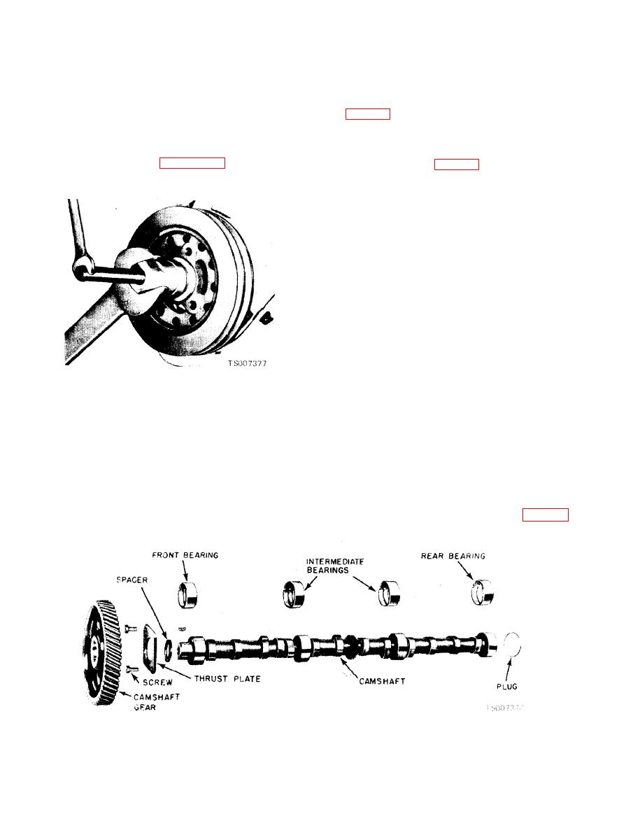
Section Vlll. CAMSHAFT AND TIMING GEARS
located between the camshaft gear and the front
6-37. General
journal on the camshaft. An eccentric, made
The camshaft is supported by four bearings,
integral with the camshaft, operates the fuel
pressed into the cylinder block. The camshaft is
pump. A gear is cast integrally with the camshaft
driven by a timing gear, pressed onto the cam-
to drive the distributor and the oil pump. The
shaft, in mesh with a gear on the crankshaft.
camshaft and related parts are shown in figure 6-
Camshaft thrust is controlled bv a thrust plate
49.
|
|
Privacy Statement - Press Release - Copyright Information. - Contact Us |
