 |
|||
|
|
|||
|
|
|||
| ||||||||||
|
|
 TM 10-3930-633-34
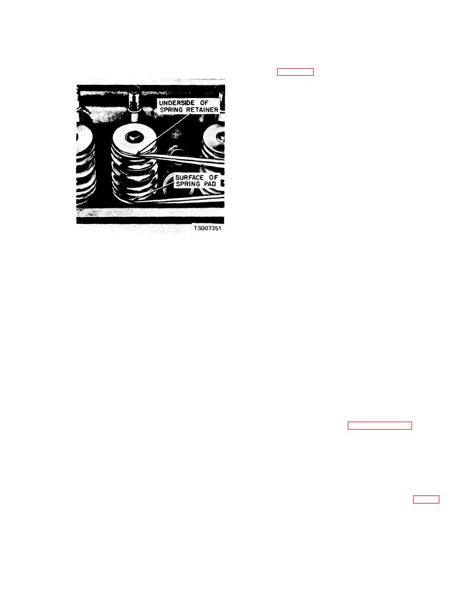
(7) Check the dividers against a scale. If the
assembled height is greater than the specified
limit (table 6-4), install the necessary 0.030 inch
thick spacer(s) between the cylinder head spring
pad and the valve spring to bring the assembled
height to the recommended dimension. Do not
install spacers unless necessary. Use of spacers in
excess of recommendations will result in over-
stressing the valve springs and overloading the
c a m s h a f t lobes which could lead to spring
breakage and worn camshaft lobes.
Section V. CYLINDER BLOCK
part dry and immediately apply a coating of zinc
oxide dissolved in wood alcohol. If cracks are
a. After any cylinder bore repair operation,
present, the coating will become discolored at the
such as honing or deglazing, clean the bore(s)
cracked area. Replace the block if it is cracked.
w i t h s o a p o r detergent and water. Then,
b. Check all machined gasket surfaces for
thoroughly rinse the bore(s) with clean water to
burrs, nicks, scratches and scores. Remove minor
remove the soap or detergent, and wipe the
imperfections with an oil stone. Check the
bore(s) dry with a clean, lint-free cloth. Finally,
cylinder block for flatness of the cylinder head
wipe the bore(s) with a clean cloth dipped in
gasket surface following the procedure and
engine oil. If these procedures are not followed,
specifications recommended for the cylinder head.
rusting of the cylinder bore(s) may occur.
The cylinder block can be machined to bring the
b. If the engine is disassembled, thoroughly
cylinder head gasket surface within the flatness
clean the block in solvent. Remove old gasket
specifications, but not to exceed 0.010 inch stock
material from all machined surfaces. Remove all
removal from the original gasket surface.
pipe plugs that seal oil passages; then clean out
c. Replace all expansion-type plugs that show
all the passages, Blow out all passages, bolt
evidence of leakage. See paragraph 6-25.
holes, etc., with compressed air.
d. Inspect the cylinder walls for scoring,
c. Make sure the threads in the cylinder head
roughness, or other signs of wear. Check the
bolt holes are clean. Dirt in the threads may cause
cylinder bore for out-of-round and taper. Measure
binding and result in a false torque reading. Use a
the bore with an accurate bore gage following the
t a p to true-up threads and to remove any
instructions of the manufacturer. Measure the
deposits.
diameter of each cylinder bore at the top, middle
and bottom with the gage placed at right angles
a. After the block has been thoroughly cleaned,
and parallel to the centerline of the engine (fig. 6-
check it for cracks. Minute cracks not visible to
23). Use only the measurements obtained at 90
the naked eye may be detected by coating the
degrees to the engine centerline when calculating
suspected area with a mixture of 25 percent
the piston to cylinder bore clearance.
kerosene and 75 percent light engine oil. Wipe the
|
|
Privacy Statement - Press Release - Copyright Information. - Contact Us |
