 |
|||
|
|
|||
|
Page Title:
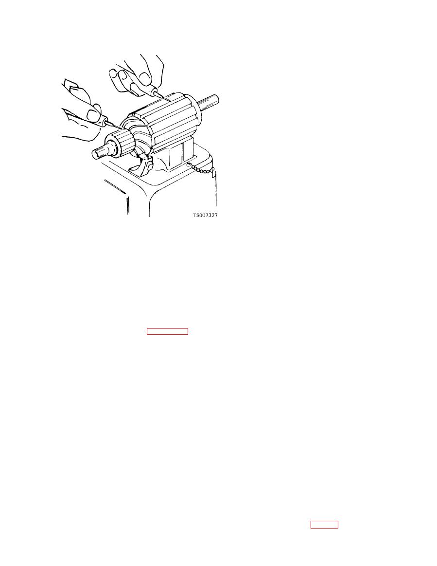
Figure 3-7. Testing for Grounds. |
|
||
| ||||||||||
|
|
 TM 10-3930-633-34
(4) To force the retainer over the snap ring,
place a suitable washer over the shaft and squeeze
the retainer and washer together with pliers.
(5) Remove the washer.
(6) Lubricate bearing of drive housing (24)
with silicon grease and install armature and drive
assembly in housing.
CAUTION
Do not lubricate solenoid plunger or
solenoid cylinder.
(7) Install return spring (7) on solenoid
plunger (8) and insert plunger into solenoid
cylinder. Apply sealing compound on both sides
of solenoid flange where it extends between drive
housing and field frame. Attach plunger to shift
lever (13) with fulcrum pin (14). Fasten solenoid
to drive housing with two mounting screws (6).
(8) If field coils were removed from field
frame, position coils of replacement field coil
assembly (28) on pole shoes and mount each pole
shoe (27) in field frame with a pole shoe screw
(26). Use care in tightening screws to avoid
distortion of parts. Be certain that screws are
(7) Check field coils with a 12-volt test lamp
securely tightened. Insert ends of field coil leads
as outlined in steps 8 and 9.
through rubber grommet in field frame.
(8) With the field coil ground disconnected,
(9) Position field frame assembly over ar-
position one test prod on the field frame and the
mature assembly so that its down pin (17)
other to the field connector. If the lamp lights, the
engages the hole in drive housing. Use care to
field coils are grounded and must either be
prevent damage to brushes and brush holders.
replaced or repaired.
Make sure that brushes (31) are properly seated
(9) If the test lamp does not light when the
on commutator.
prods are connected to the ends of coil leads, the
(10) Install leather thrust washer (23) on
field coils are open.
commutator end of armature assembly. Lubricate
bearing in commutator end frame with silicon
(1) Place the drive pinion assembly (18) on
grease and position end frame to field frame so
the armature shaft.
that armature shaft enters bearing. Secure field
(2) To aid in reinstalling the snap ring (20)
frame and end frame to drive housing with two
and collar (21 ) on the armature shaft, proceed as
through bolts (15). Connect field leads to motor
follows. Place the collar (21 ) on the armature
terminal of solenoid with screw (4).
shaft with the cupped surface facing the snap ring
e. Installation and Testing. Refer to TM 10-
groove.
3930-633-12 for procedures covering installation
(3) Place the snap ring (20) on the end of the
and testing of the starter assembly.
shaft. With a piece of wood on top of ring, force
the ring over the shaft with a light hammer blow,
then slide the ring down into the groove.
Section III. IGNITION DISTRIBUTOR
3-7. General
the ignition timing at higher engine speeds or
heavy engine loadings to provide the correct
The distributor is equipped with both vacuum
ignition timing for maximum engine performance.
and centrifugal advance units. The vacuum
The advance mechanisms are independently
advance governs the ignition timing (spark
operated,
advance) during low engine speeds (RPM ) or low
a. Centrifugal Advance. The centrifugal ad-
engine loadings, The centrifugal advance, in
vance mechanism (fig. 3-8) is located below the
combination with the vacuum advance, controls
|
|
Privacy Statement - Press Release - Copyright Information. - Contact Us |
