 |
|||
|
|
|||
|
Page Title:
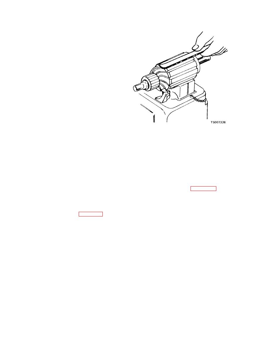
Figure 3-6. Testing for Shorts. |
|
||
| ||||||||||
|
|
 TM 10-3930-633-34
(6) Remove the pinion from the armature by
sliding a metal cylinder onto the shaft; with a
hammer striking the metal cylinder against the
retainer, drive the retainer toward the armature
core and off the snap ring (20).
(7) Remove the snap ring (20) from the
groove in the armature shaft.
(8) Roll type drive pinion assemblies (18) are
designed to be serviced as a complete unit;
therefore, do not disassemble. If the condition of
the clutch assembly is questionable, replace it.
(9) A pole shoe spreader and pole shoe
screwdriver should be used if the field coils are to
be removed. Extra caution should be taken in
replacing the field coils to prevent grounding or
shorting when they are tightened in place. If the
pole shoe has a long lip on one side, it should be
assembled in the direction of armature rotation.
c. Inspection and Repair.
(1) Inspect the brushes for wear. If they are
worn down to one-half their original length, when
compared with a new brush, they should be
replaced. New brushes are ?/2, inch long.
(5) Opens are usually found where the
(2) Clean brush holders and be sure that the
conductors are joined to the commutator. Loose
brushes will not bind in the holders. The full
or poor connections will cause arcing and burning
length of the brush surface should ride on the
of the commutator. If the bars are not burned too
commutator with the proper spring tension (40
bad, resolder the leads in the riser bars and turn
ounces) to provide a good contact. Inspect the
the commutator down in a lathe. Then undercut
brush leads and screws to be sure they are tight
the insulation between the commutator bars 1/32
and clean.
inch .
(3) Inspect the armature to be sure there are
(6) Grounds in the armature can be found
no short circuits, opens, or grounds (see steps 4,
using a test lamp and prods, figure 3-7. If the
5 and 6 following).
lamp lights when one prod is positioned on the
(4) Short circuits are located by turning the
armature core or shaft, the armature is grounded.
armature in a growler while holding a steel strip
on the armature. The steel strip will vibrate on
the area of the short circuit. See figure 3-6.
|
|
Privacy Statement - Press Release - Copyright Information. - Contact Us |