 |
|||
|
|
|||
|
|
|||
| ||||||||||
|
|
 TM 10-3930-633-34
care to avoid misalignment or otherwise placing
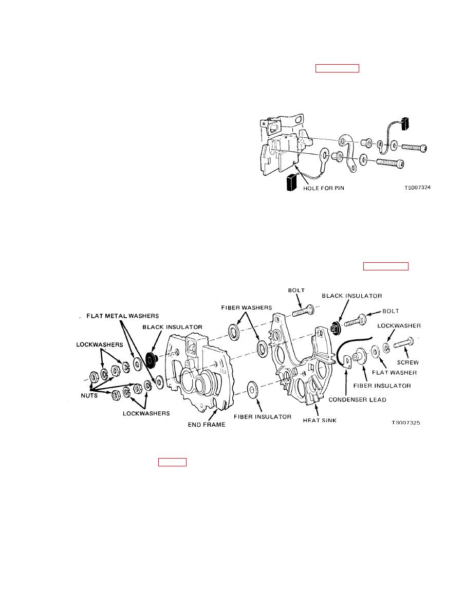
attach the brush holder assembly onto the end
undue stress on the bearing.
frame, noting carefully the proper stack-up of
(5) Saturate the felt seal with S.A.E. 20 oil,
parts as shown in figure 3-3. Allow the straight
and then reassemble the felt seal and steel
wire to protrude through the hole in the end
retainer.
frame.
j. Brush Replacement.
(1) When the slipring end frame assembly is
separated from the rotor and drive end frame
assembly, the brushes will fall down onto the
shaft and come in contact with the lubricant. If
the brushes are to be re-used, they must be
thoroughly cleaned with a soft dry cloth. Also,
the shaft must be thoroughly cleaned before
reassembly.
(2) The brush springs should be inspected
for any evidence of damage or corrosion. If there
is any doubt as to the condition of the brush
springs, they should be replaced.
(3) To install new brushes, remove the brush
k. Heat Sink Replacement. The heat sink may
holder assembly from the end frame by detaching
be replaced by removing the "BAT" and "GRD"
the two brush holder assembly screws. Install the
terminals from the end frame, and the screw
springs and brushes into the brush holder, and
attaching the condenser lead to the heat sink.
insert a straight wire or pin into the holes at the
During reassembly, note carefully the proper
bottom of the holder to retain the brushes. Then
stack-up of parts as shown in figure 3-4.
remove tape over the bearing and shaft. Make
l.
sure shaft is perfectly clean.
shown in the exploded view (fig. 3-1). Note the
(3) Insert a straight wire as previously
following procedures:
mentioned through holes in brush holder and end
(1) Hold rotor with hex key wrench in end of
frame to retain the brushes. Remove the wire
shaft and tighten pulley nut to 60 ft/lbs. If pulley
after the a.c. generator has been completely
is held in vise and excessive pressure is applied
assembled. The brushes will then drop into place
against rotor, t h e assembly may become
on sliprings.
distorted.
m. Installation and Testing. Refer to TM 10-
(2) When installing slipring end frame
3930-633-12 for installation and testing
assembly to rotor and drive end frame assembly,
procedures.
|
|
Privacy Statement - Press Release - Copyright Information. - Contact Us |