 |
|||
|
|
|||
|
Page Title:
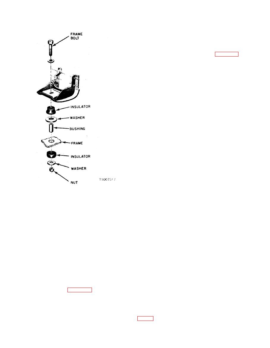
Figure 2-2. Engine Front Support. |
|
||
| ||||||||||
|
|
 TM
10-3930-633-34
Lower engine fully on front support and remove
lifting sling.
(5) Install frame bolt and nut through engine
front support. Torque to 35 to 50 ft/lbs.
(6) Position the transmission oil filter
assembly on the bracket as shown in figure 2-1,
and install the three screws to secure filter to
bracket. Install clips over oil lines on engine
block.
(7) Install the starter (see TM 10-3930-633-
12). Connect starter cables, and install the
transmission filler tube bracket.
(8) Attach the exhaust pipe to the manifold
flange. Torque the nuts to 25 to 35 ft/lbs.
(9) Connect the engine ground strap.
(10) Connect the vacuum line at the intake
manifold. Connect the choke cable and accelerator
cables to the carburetor and anchor brackets. Be
sure the retracting spring is properly installed.
(11 ) Connect the engine wiring harness at
the coil, vacuum switch, coolant temperature
sender, and oil pressure sender.
(12) Install the alternator (see TM 10-3930-
633-12) but do not tighten mounting bolts.
(13) Install radiator (see TM 10-3930-633-
12). Connect oil cooler lines and install upper and
lower radiator hoses.
(14) Install fan pulley, fan belts and fan.
Torque fan bolts to 40 to 45 ft/lbs.
(15) Adjust fan belt tension and tighten
alternator mounting bolts (see TM 10-3930-633-
12).
(16) Install air cleaner ductwork. Connect
(18) Attach a sling to the engine or lifting
hose to fuel pump.
eyes, and tighten the hoist arrangement to bear
(17) Install and adjust hood.
most of the engine weight.
(18) Connect battery cables.
(19) Remove all converter housing to engine
(19) Fill and bleed cooling system. Fill the
attaching screws. Raise the engine slightly and
engine crankcase (see TM 10-3930-633-12). Start
slide forward to disengage crankshaft from torque
the engine check for leakage. Adjust idle speed
converter.
and mixture.
(20) Lift engine carefully and guide by hand
to avoid striking parts of the engine against the
2-25. Transmission
frame. If any resistance is felt, stop hoist im-
a. Removal.
m e d i a t e l y a n d investigate c a u s e before
(1) Remove the screws along the floor plate,
proceeding.
a n d lift off the transmission cover in the
b. Installation.
o p e r a t o r ' s compartment. Disconnecting the
accelerator pedal will simplify removal of the
pipe.
transmission cover.
(2) Lower the engine carefully into place on
(2) Disconnect the parking brake link from
the chassis. Make sure that front mount parts are
the brake lever mechanism, and swing the
arranged as shown in figure 2-2.
transmission cover up and out of the way.
(3) Observe the engine to transmission
(3) Disconnect the push-pull control cable at
converter housing flange and make sure that the
the transmission linkage on the side of the
converter pilot enters the crankshaft and that the
transmission case. Remove locknuts from cable
dowel pins in the engine block engage the con-
housing to free the cable from the anchor bracket
verter housing holes properly.
(4) Install engine to converter housing bolts.
|
|
Privacy Statement - Press Release - Copyright Information. - Contact Us |
