 |
|||
|
|
|||
|
Page Title:
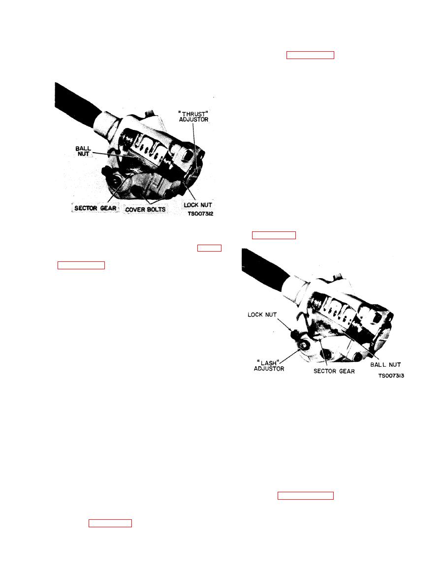
Figure 4-60. Steering Gear Thrust Adjustment |
|
||
| ||||||||||
|
|
 TM 10-3930-633-12
bearings, loosen locknut and then turn worm
CAUTION
bearing adjuster nut clockwise until all end play is
Approach extreme ends cautiously;
removed see figure 4-60. Using spring scale, as
worm ball nut must not strike ends with
directed in step (2), check pull and readjust as
any degree of force.
necessary; then tighten locknut securely.
c. Sector Gear Lash Adjustment.
(1) Steering gear mechanism must be in
straight ahead position as previously explained.
(2) Turn lash adjuster screw clockwise to
remove all lash between gear teeth. Tighten
adjuster screw locknut. Position spring scale on
steering wheel so pull may be made at right
angles to wheel spoke.
(3) Measure pull while wheel is TURNED
THROUGH CENTER POSITION. Readjust if
reading is not within 2 to 3 pounds.
(4) Tighten adjuster screw locknut, check
pull again.
(5) After adjustments are made, install drag
link on pitman arm.
NOTE
If steering linkage adjustment is necessary, do not
install drag link to pitman arm. Refer to
b. Steering Gear Thrust Adjustment.
(1) Check tightness of cover bolts see figure
4-60. Loosen locknut and turn lash adjuster screw
see figure 4-61 counterclockwise a few turns to
provide clearance between sector gear and worm
ball nut.
(2) Turn steering wheel GENTLY to one
extreme end. Turn wheel back one full turn. With
spring scale on spoke of wheel, measure pull
required to KEEP WHEEL MOVING. Pull on
scale should be made at right angles to wheel
spoke. If pull is within 1 to 2 pounds, proceed
to lash adjustment in the following paragraphs. If
pull is not within 1 to 2 pounds, adjust worm
bearings. The pitman shaft adjustment must be
made if worm bearing check is accomplished, or if
the worm bearings are adjusted.
(3) If it is necessary to adjust the worm
Section XVIII. MAINTENANCE OF FRONT AXLE AND SPRINGS
4-89. Inspection
4-88. General
a. Check for bent front axle, loose or damaged
The front axle is a light truck type, being a solid
U-bolts at spring pads.
I-beam with front wheel steering spindles at-
b. Check springs for broken leaves, loose or
tached directly at each end. The axle is suspended
damaged spring shackles.
below the frame by means of semi-elliptical leaf
springs. The steering spindles are attached by
justment (paragraph 4-75).
means of king pins through the knuckle and axle.
d. Check steering linkage parts for physical
A thrust bearing is used between the lower face of
damage and secure attachment.
the axle and the steering knuckle to reduce
friction (see figure 4-62).
|
|
Privacy Statement - Press Release - Copyright Information. - Contact Us |
