 |
|||
|
|
|||
|
|
|||
| ||||||||||
|
|
 TM 10-3930-633-12
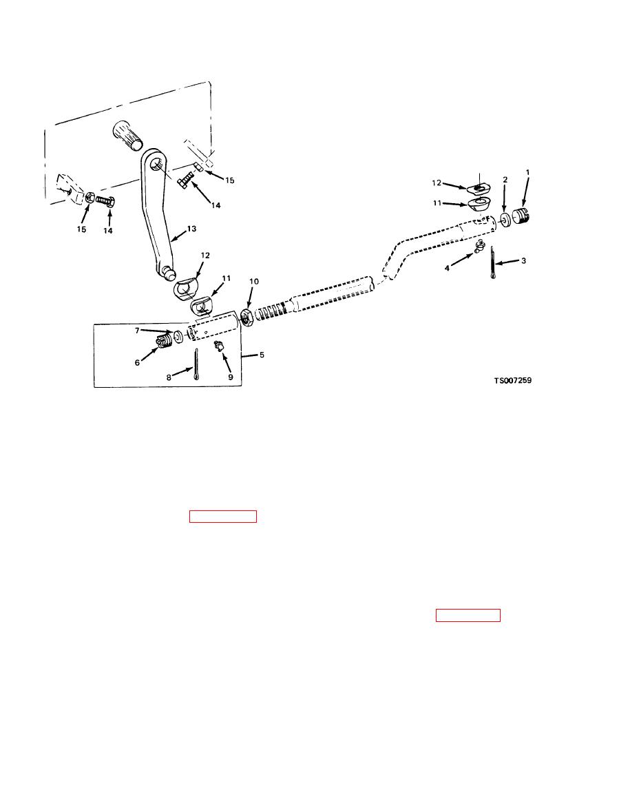
6. Adjusting plug
1. Adjusting plug
11. Seal
7. cup
12. Shield
2. cup
13. Pitman arm
3. Cotter pin
8. Cotter pin
14. Stop screw
4. Lubrication fitting
9. Lubrication fitting
15. Locknut
5. Socket assembly
10. Nut
d. Repair and Replacement.
a. Before making above adjustments, the
following preliminary operations" are necessary.
(1) Repair of the drag link consists of
replacement of any part see figure 4-59 found
(1) Disconnect steering drag link from
pitman arm. Note relative position of drag link
defective after removal and disassembly.
parts when disconnecting link so the parts may be
(2) TO remove the drag link, remove cotter
re-assembled correctly.
pin from each socket end, and loosen plugs until
(2) Check lubricant level. in steering gear
enough clearance is obtained to pull the sockets
housing. If low, add enough lubricant to bring
free of the ball studs.
level up to filler plug hole. See LO 10-3930-633-12.
(3) Further disassembly is accomplished as
(3) Tighten steering gear housing to frame
indicated by the exploded view illustration.
side member bolts. See figure 4-60.
(4) Adjust drag link overall length as
(4) Determine straight-ahead position of
outlined in the preceding paragraph before in-
steering mechanism by turning steering wheel to
stalling. Make certain both ball sockets are
extreme right. Then turn to extreme left,
properly lubricated. See LO 10-3930-633-12.
counting the exact number of turns from right to
left end. Turn wheel back one-half number of
Steering gear adjustments must be made ONLY
wheel turns. Mark wheel with respect to steering
as outlined in the following steps. Refer to figures
column so center position may readily be found
4-60 and 4-61. Always check worm bearing thrust
during adjustment procedures.
adjustment, and adjust if necessary, before
making sector gear lash adjustment.
|
|
Privacy Statement - Press Release - Copyright Information. - Contact Us |
