 |
|||
|
|
|||
|
Page Title:
Figure 4-37. Parking brake, exploded view. |
|
||
| ||||||||||
|
|
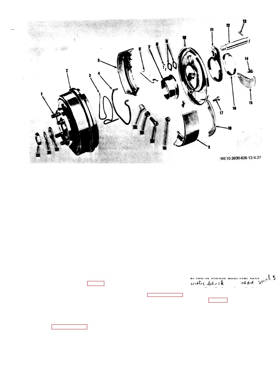 1.
Stud
14,
Screw
2.
Brake drum
1.5.
Adjustment cover plate
3.
Spring retainer
16.
Sleeve
4.
Return spring
17.
Screw
5.
Brake shoe
18.
Lever
6.
Operating lever strut
19.
Nut
7.
Shield
20.
Adjustment screw
8.
Guide retainer
21.
Adjustment nut
9.
Guide
22.
Sleeve
10.
Support
23.
Washer
11.
Spacer
24.
Washer
12.
Anchor
25.
Nut
13.
Pin
b. Parking Brake,
adjusting nut (21) one notch at a time until parking
brake lever can be properly adjusted.
( 1 ) Adjustment.
(a) Remove rear floor plate from tractor
(g) Replace cover plate (15) and screw (14).
chassis.
(2) Shoe removal.
(a) Raise rear end of vehicle until rear tires
(b) Release parking brake leverl.
(c) Remove screw (14, fig. 4-37) and ad-
clear
floor.
justing screw cover plate (15).
(d) Turn adjusting nut (21) until brake
shoes (5) fully contact brake drum (2).
(c) Remove nut (25, fig. 4-37), and washers
(e) Back off adjusting nut six notches.
(24 and 23) securing brake drum (2), and with
parking brake lever released, remove brake drum.
c Note. Be certain two raised shoulders on adjusting
nut are seated in grooves on adjusting sleeve (22).
(d) Disengage ball end of parking brake
(f) Apply parking brake lever and adjust as
cable from level (18).
described in paragraph 4-55a(1) above. If parking
(e) Separate brake shoes (5) at bottom
brake lever cap adjustment is exceeded, readjust
|
|
Privacy Statement - Press Release - Copyright Information. - Contact Us |
