 |
|||
|
|
|||
|
Page Title:
Section VII. Maintenance of Positive Crankcase Ventilation System |
|
||
| ||||||||||
|
|
 Section VII.
MAINTENANCE
OF
POSITIVE
VENTILATION
SYSTEM
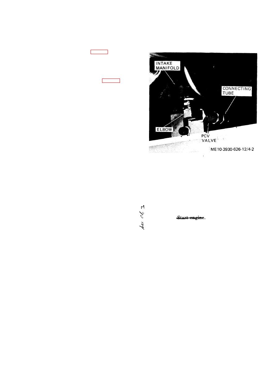
4-19. General
f. Connect tube to fitting at rear of engine block
a n d to lower end of PCV valve. Tighten con-
The positive crankcase ventilation valve
(PCV
nections securely.
valve) is located on the right side of the
engine
below the intake manifold (fig. 4-2). An
elbow
connects the valve to the intake manifold
and a
connecting tube connects the valve to the
engine
block.
4-20. Service and Replacement
lower end of PCV valve, then unscrew valve from
elbow.
b. Disconnect other end of connecting tube at
rear of engine block, and remove tube.
c. Thoroughly flush valve in both directions and
flush tube with SD (solvent, dry-cleaning, Fed.
Spec. P-S-661 ). Shake valve and tube vigorously to
remove cleaning solvent.
d. After cleaning, gently shake valve to determine
that check is free.
Note. Replace PCV valve if check is not free or if valve
shows evidence of internal corrosion.
e. Screw valve onto manifold elbow, being sure to
observe proper flow direction ( e n g i n e block to
manifold). Tighten securely.
Section V I I I .
MAINTENANCE
OF
BASIC
ENGINE
4-21. General
the condition of the piston rings and engine valves
An engine without fairly even compression in al
a. The engine is a six cylinder L-head unit, with
cylinders cannot be properly tuned.
battery ignition. The cooling system includes a
b. Procedure.
front-mounted water pump driven by a V -belt
(1) With shift lever in N (neutral) position,
from the crankshaft, a radiator mounted in front of
start engine.
Allow engine to run at
the engine, and a thermostat in the cylinder head
f a s t idle until reaching normal operating tem-
water outlet to maintain a constant efficient engine
perature.
operating temperature. The ignition system consists
(2) With engine warmed up, turn off ignition
of a coil, a conventional distributor, resistor spark
switch and remove spark plug wires from spark
plugs, the necessary wiring and cabling, and radio
plugs. Remove foreign matter from around spark
interference suppression components. The engine
plugs by blowing out with compressed air. Loosen
fuel system includes a mechanical fuel pump, a
spark plugs one complete turn. Reinstall spark plug
velocity governor, a downdraft singlebore car-
cables, and start and run engine at 1000 rpm for
buretor with air cleaner, and the required fuel lines
a p p r o x i m a t e l y 10 seconds to blow out carbon
and manifolding. Cylinder, spark plug and bearing
loosened by spark plug loosening.
numbering begins at the timing gear, or fan end, of
the engine.
Note. Blowing out carbon in this manner is important
in preventing false compression readings due to chips of carbon
b. This section of the manual covers those phases
lodging under the engine valves.
o f b a s i c engine maintenance which a r e the
(3) Turn off ignition switch to stop engine.
responsibility of organizational maintenance.
(4) Remove coil high tension lead from
distributor cap and ground lead to engine block.
a. General. P e r f o r m a c o m p r e s s i o n t e s t t o
(5) Remove spark plug leads from spark plugs,
determine the need of internal repairs before at-
and remove spark plugs from cylinder head.
tempting tune-up procedures. This test will indicate
(6) Fully open carburetor throttle and choke
|
|
Privacy Statement - Press Release - Copyright Information. - Contact Us |
