 |
|||
|
|
|||
|
Page Title:
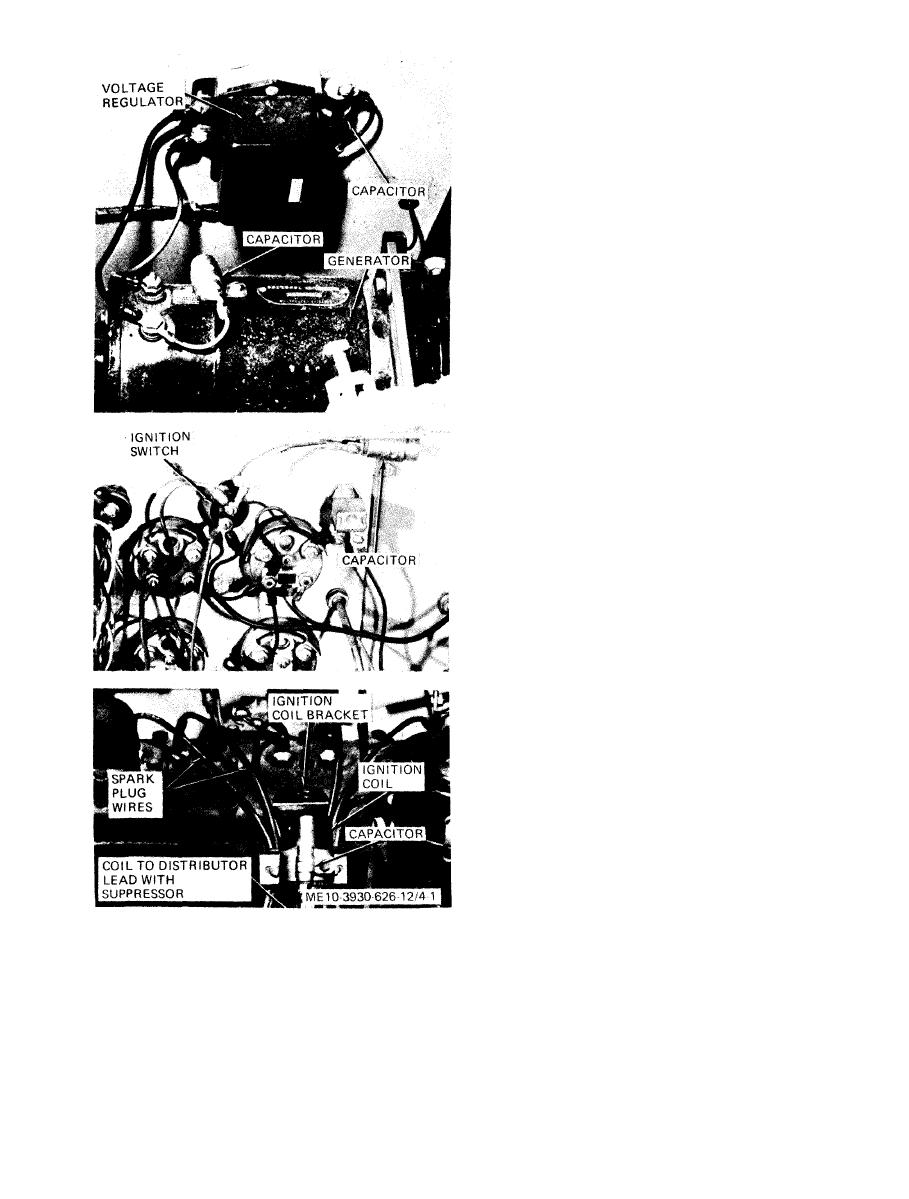
Figure 4-1. Radio interference suppression components. |
|
||
| ||||||||||
|
|
 s e c u r e s lead to capacitor terminal and remove
screw and lock washer which secure capacitor to
generator frame. To install capacitor, reverse the
removal procedure.
c. Regulator Capacitor. Remove screw which
secures lead to capacitor terminal, and remove
screw and self-locking nut used to mount capacitor.
Withdraw capacitor. To install capacitor, reverse
the removal procedure.
d. Ignition Coil Capacitor. Remove screw which
secures lead to terminal, and remove cap screw, nut
and lock washer which secure capacitor to coil
mounting strap. To replace capacitor, reverse the
removal procedure.
e. Ignition Switch Capacitor. R e m o v e s c r e w
which secures lead to capacitor terminal. Remove
self-locking n u t s e c u r i n g c a p a c i t o r t o t r a c t o r
chassis. Withdraw capacitor. To replace capacitor,
reverse the removal procedure.
f. Coil to Distributor Lead. Grasp coil to
distributor lead firmly near coil, and pull lead free
from coil. Grasp lead firmly near distributor cap,
and pull lead free from cap. To install new lead,
reverse the removal procedure. Assure that nipples
(boots) on ends of lead form a good dust-tight seal
with coil and distributor cap.
g. Spark Plug Wires. Replace wires one at a time
to avoid wrong connections between distributor cap
and spark plugs. Grasp each wire firmly at
d i s t r i b u t o r cap, and pull wire free from cap.
Remove nipple (boot) from free end of wire. Pull
wire free from slot in ignition coil bracket. Grasp
wire firmly at spark plug terminal end, and pull
free from spark plug. To install wires, reverse the
removal procedure. Check that nipples (boots) on
wires at distributor cap form tight seals.
Capacitors
4-18.
Testing Suppression
Each of the suppression capacitors has a
capacitance rating of 0.10 uf. Use a capacitor tester
to check each capacitor after removal from tractor.
|
|
Privacy Statement - Press Release - Copyright Information. - Contact Us |