 |
|||
|
|
|||
|
|
|||
| ||||||||||
|
|
 c. Inspection and Repair.
( 1 ) Inspect valve housing and valve for nicks,
burrs, pitting, a n d w e a r . E x a m i n e t h e v a l v e s e a t
and valve for damage and proper seating. If wear or
damage
replace
exists,
the
valve
complete
assembly.
( 2 ) Inspect the check valve spring for damage
a n d proper tension. T h e check valve spring should
e x e r t 5.750.50 pounds of force when compressed
to 2 . 0 0 i n c h e s . F r e e l e n g t h a f t e r t e s t s h o u l d b e
3 . 2 8 1 inches. Spring diameter is 0.50 inch. Replace
d e f e c t i v e or weak spring.
NOTE
Transmission
a. General.
power s h i f t t r a n s m i s s i o n utilizes
(1)
The
p l a n e t a r y gearing and five hydraulically actuated
clutches to provide three forward and three reverse
speeds.
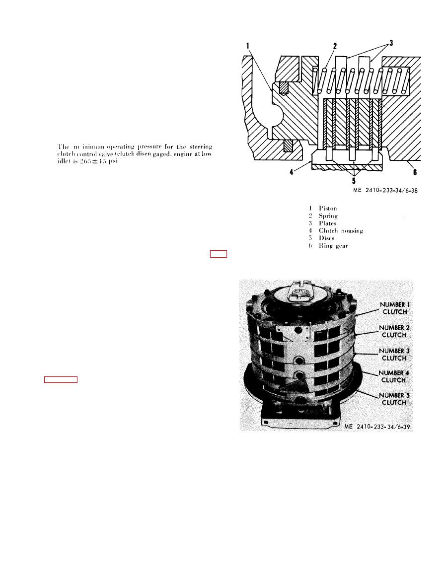
( 2 ) The five transmission clutches are of the
m u l t i p l e disc type, and are contained in separate
h o u s i n g s surrounding the ring gears of the trans-
m i s s i o n . The clutches have alternate discs (5, fig.
6-38) and plates (3). The discs (5) have internal
t e e t h which mesh with external teeth on the ring
g e a r (6). The plates (3) are notched to fit around
pins in the clutch housings which prevent the plates
from turning.
(3) The clutches are held disengaged by
s p r i n g s (2) which act between the clutch housing
(4) and piston (1). To engage the clutch, oil is
directed into the space behind the piston (1).
h y d r a u l i c pressure then moves the piston outward,
p r e s s i n g the plates (3) and discs (5) together and
preventing the ring gear (6) from turning.
( 4 ) The two front clutches (No. 1 and No. 2,
fig. 6 - 3 9 ) a r e d i r e c t i o n a l c l u t c h e s , d e t e r m i n i n g
forward or reverse direction, and the three rear
cluthes (No. 3. No. 4 and No.
5) are speed
clutches providing second, third and first speed
respectively.
( 5 ) Two clutches must be engaged in order to
transmit power through the transmission. The
f o l l o w i n g chart shows the combination of clutches
e n g a g e d for each forward or reverse speed.
b.
Transmission
Reconditioning.
Speed
Clutches engaged
( 1 ) Before disassembling the transmission, all
d i r t and grease accumulations should be removed
1-5
First forward
from the exterior of the transmission case. The
1-3
Second forward
should be disassembled and
transmission
1-4
Third forward
2-5
a s s e m b l e d in clean surroundings with clean tools.
First reverse
2-3
Second reverse
D i r t or grit introduced into the transmission will
2-4
Third reverse
cause erratic operation and will shorten the service
l i f e of the transmission.
|
|
Privacy Statement - Press Release - Copyright Information. - Contact Us |
