 |
|||
|
|
|||
|
Page Title:
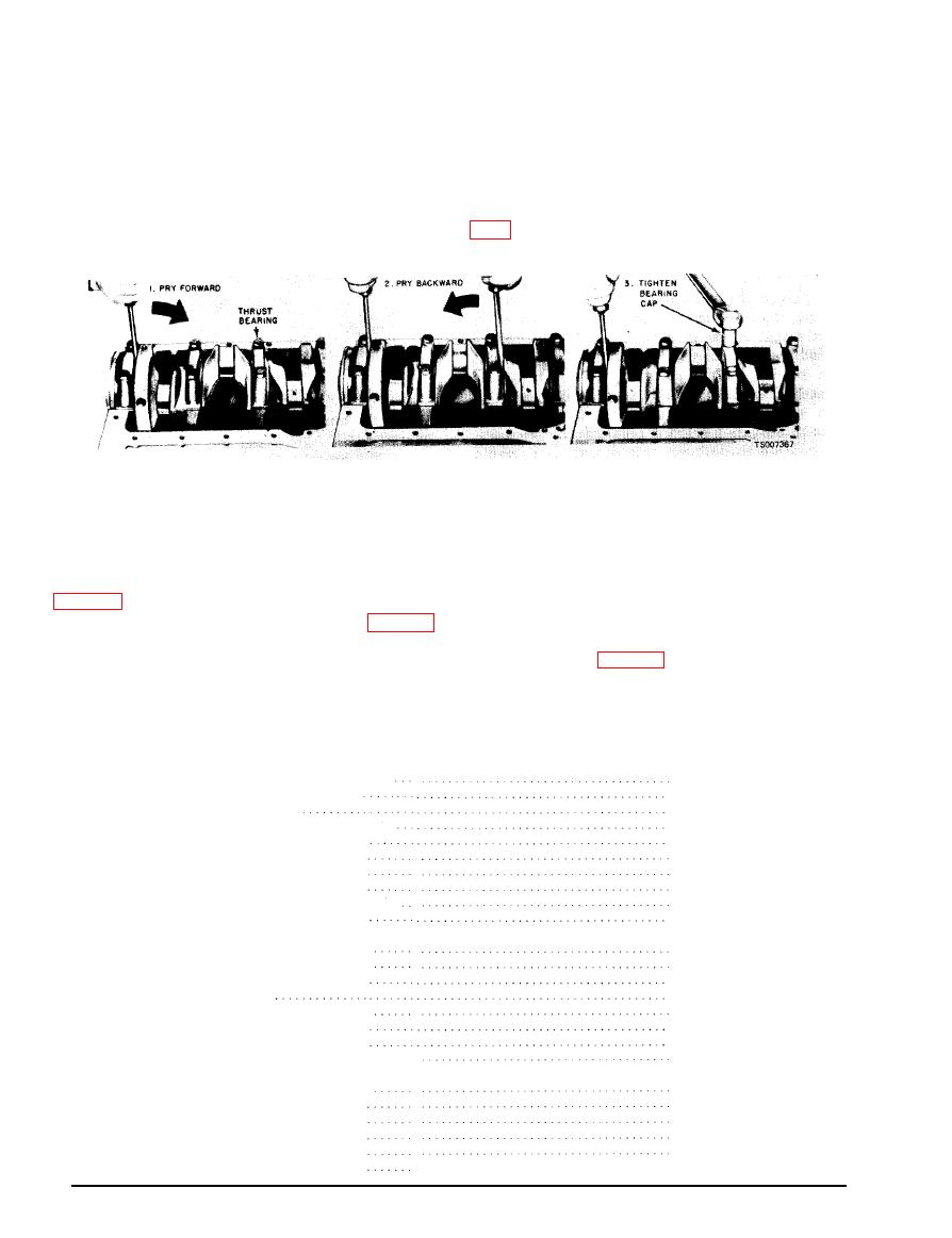
Figure 6-38. Aligning Thrust Bearings. |
|
||
| ||||||||||
|
|
 TM 10-3930-633-34
under Fitting Main and Connecting Rod
installed in their original locations. Torque the
Bearings.
bearing cap bolts to specifications.
(10) Install the thrust bearing cap with the
(9) After the bearings have been installed,
bolts finger-tight.
apply a light coat of heavy engine oil to the
journals and bearings. Install all the bearing
(11 ) Pry the crankshaft forward against the
thrust surface of the upper half of the bearing (fig.
caps, except the thrust bearing cap (No. 5
bearing). Be sure that the main bearing caps are
than the minimum limit, inspect the thrust
(12) Hold the crankshaft forward and pry the
bearing faces for scratches, burrs, nicks or foreign
thrust bearing cap to the rear. This will align the
matter. If the thrust faces are not damaged or
thrust surfaces of both halves of the bearing.
(13) Retain the forward pressure on the
dirty, they probably need realigning. Install the
crankshaft. Torque the cap bolts to specifications
thrust bearing and align the faces following the
recommended procedure (steps 8 through 11).
Then check the end play.
(14) Check the crankshaft end play (para 6-
34).
(16) Coat a new crankshaft rear oil seal with
oil and install it (fig. 6-39). Inspect the seal to be
(15) If the end play exceeds the wear limit,
replace the thrust bearing. If the end play is less
sure it was not damaged during installation.
ITEM
INCHES
CRANKSHAFT
Main bearing journal diameter
.2.3982-2.3990
..0.0004
M a x i m u m out-of-round
..0.005
Wear limit . . . .
. . . 0.002
Main bearing journal runout maximum
.0.0003
Maximum journal taper (per inch)
.1.199-1.201
Thrust bearing journal length.
. :2.1228-2.1236
Connecting rod journal diameter
.0.004 -0.008
Crankshaft end play
.. 0.005 T.I.R.
Crankshaft to rear face of block runout
.. 0.040
Flywheel ring gear lateral runout.
CONNECTING ROD
. .0.9734-0.9742
Piston pin bushing I.D.
Rod bearing bore diameter . . . . .
. .2.2750-2.2758
maximum out-of -round . . . .
. . . 0.0006
.0.0004
maximum taper .
. 6.7932-6.7962
Center-to-center length . . . . . . . . . . . .
. ...012
Maximum
twist
Maximum
bend.....
. ..004
Side clearance (assembled to crankshaft)
..0.0060-0.0130
BEARINGS
. .0.0754-0.0757
Connecting rod (wall thickness-std).
0.0008-0.0015
desired
clearance
. .0.0008-0.0024
allowable
clearance
Main bearings (wall thickness-std) . . . .
. .0.0954-0.0957
desired
clearance
. .0.0005-0.0015
allowable clearance .
. .0.0005-0.0022
|
|
Privacy Statement - Press Release - Copyright Information. - Contact Us |
