 |
|||
|
|
|||
|
Page Title:
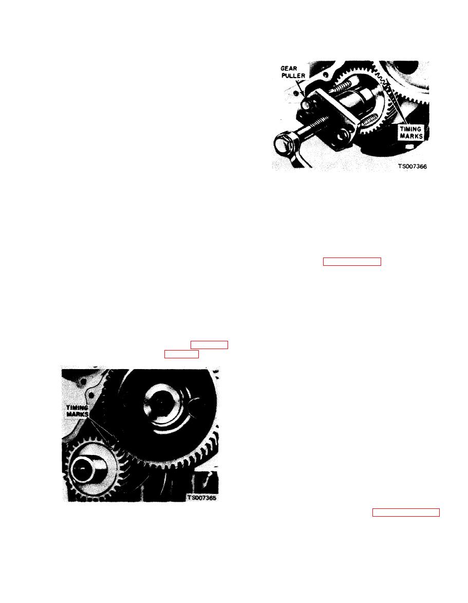
Figure 6-37. Removing Crankshaft Gear. |
|
||
| ||||||||||
|
|
 TM 10-3930-633-34
(4) Remove the cylinder front cover and
gasket.
(5) Remove the flywheel and engine rear
cover plate.
(6) Turn the engine on the work stand so that
the bottom of the engine is up. Remove the oil
pan, gaskets and seals. Remove the oil pump and
inlet tube assembly. Discard the oil pump gasket.
(7) Use an awl to punch two holes in the
crankshaft rear oil seal. Punch the holes on op-
posite sides of the crankshaft and just above the
bearing cap to cylinder block split line. Install a
sheet metal screw in each hole. Use two large
screwdrivers or small pry bars and pry against
both screws at the same time to remove the
crankshaft rear oil seal. It may be necessary to
place small blocks of wood against the cylinder
(10) Remove the main bearing caps and
block to provide a fulcrum point for the pry bars.
bearings.
Use caution throughout this procedure to avoid
(11) Carefully lift the crankshaft out of the
scratching or otherwise damaging the crankshaft
cylinder block so that the thrust bearing surfaces
oil seal surface.
are not damaged. Handle the crankshaft with care
(8) Make sure all bearing caps (main and
to avoid possible fracture or damage to the
connecting rod) are marked so that they can be
finished surfaces.
installed in their original locations. Turn the
(12) Refer to paragraph 6-30 for the cleaning
crankshaft until the connecting rod from which
and inspection procedures. Be sure the oil seal
the cap is being removed is at the bottom of the
surfaces on the crankshaft and crankshaft damper
stroke. Remove the connecting rod cap and
are properly cleaned.
bearings. Push the connecting rod and piston
b. Installation.
assembly up in the cylinder. Do not turn the
(1) Remove the main bearing inserts from the
crankshaft completely around as the rod bolts
block and bearing caps.
may damage the crankpin journals. Repeat this
(2) Remove the bearing inserts from the
procedure and remove all connecting rod caps.
connecting rod caps.
(3) Clean the crankshaft rear oil seal recess in
(9) Align the timing marks (fig. 6-36).
the cylinder block and rear main bearing cap.
Remove the crankshaft gear (fig. 6-37).
(4) If the crankshaft main bearing journals
have been refinished to a definite undersize,
install the correct undersize bearings. Be sure the
bearing inserts and bearing bores are clean,
Foreign material under the inserts will distort the
bearing and cause a failure.
(5) Place the upper main bearing inserts in
position in the bore with the tang fitting in the
slot provided. Be sure the oil holes in the bearing
inserts are aligned with the oil holes in the
cylinder block transverse webs.
(6) Install the lower main bearing inserts in
the bearing caps with the tang fitted in the slot.
(7) Carefully lower the crankshaft into place.
Be careful not to damage the bearing surfaces.
(8) Check the clearance of each main bearing
following procedures given in paragraph 6-33
|
|
Privacy Statement - Press Release - Copyright Information. - Contact Us |
