 |
|||
|
|
|||
|
Page Title:
Section IV. CYLINDER HEAD AND VALVES |
|
||
| ||||||||||
|
|
 TM 10-3930-633-34
sequence to specifications. Install the crankcase
cylinder firing position and install the distributor. With
the distributor ignition points open position (No. 1 cyl-
ventilation regulator valve in the rocker arm cover.
inder) install the hold-down clamp and screw. Tighten
Attach the vent hose to the intake manifold inlet tube.
the screw snug, but not tight.
(34) Install the cylinder block drain plugs and oil
(38) Use a new gasket and install the fuel pump.
pressure sending unit. Install the oil level dipstick tube
Torque the bolts to specifications, Install the carbure-
and dipstick.
tor fuel inlet line and distributor vacuum line.
(35) Install the oil filter mounting adapter, Coat
(39) Install the distributor cap and spark plug
the seal surface of a new oil filter with grease (or en-
wires. Connect the spark plug wires. Connect the dis-
gine oil). Install the oil filter until the seal surface
tributor primary and secondary high tension wires to
contacts the cylinder block, then tighten the filter an
the ignition coil.
additional turn.
(40) Remove the engine from the work stand.
(36) Install the ignition coil and bracket.
Install the engine front support.
(37) Position No. 1 cylinder on TDC after the
compression stroke. Set the distributor points to No. 1
Section IV. CYLINDER HEAD AND VALVES
6-13. General
as the stud nut is tightened (6-7.2). When the push rod
to rocker arm clearance has been eliminated, tighten
head carries the valves,
The cylinder
the stud nut an additional 1 turn to place the hydraulic
individually-mounted valve rocker arms, manifold
lifter plunger in the desired operating range.
assembly, coolant outlet housing and thermostat.
Valve guides are cast integrally in the head. The valve
arrangement, from front-to-rear, is exhaust-intake for
each cylinder.
Valve clearance should be set to zero lash at each
1000 hours of operation, or whenever rough engine
idle or noisy lifters indicate the need for this
procedure.
a. Install an auxiliary starter switch, Crank the
engine with the ignition switch OFF.
b. Make 2 chalk marks on the crankshaft damper
degrees apart so that, with the timing mark, the
damper is divided into three equal parts (120 degrees
is 1/3 of the distance around the damper
circumference).
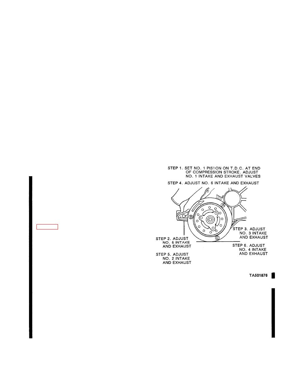
c. Rotate the crankshaft until No. 1 piston is on
TDC at the end of the compression stroke. Check the
breakaway torque (torque required to turn nut in a
counterclockwise direction) of each stud nut. Replace
the stud nut if the breakaway torque does not meet
specifications. If, after replacing the stud nut, the
breakaway torque still is not within specifications,
e. Repeat this procedure for the remaining set of
replace the stud.
valves, turning the crankshaft with an auxiliary starter
switch, 1/3 turn at a time, in the direction of rotation,
d. With No. 1 piston on TDC at the end of the
while adjusting the valves in the firing order sequence,
compression stroke, adjust the intake and exhaust
1-5-3-6-2-4. This procedure requires 2 complete turns
valve clearance for No. 1 cylinder. Loosen the rocker
of the crankshaft.
arm stud nut until there is end clearance in the push
f. Operate the engine and check for rough engine
rod, then tighten the nut to just remove all the push
idle or a noisy lifter(s). Valve clearance set too tight
rod to rocker arm clearance. This may be determined
will cause rough idle and valve clearance set too loose
by rotating and/or moving the push rod with the fingers
Change 1
|
|
Privacy Statement - Press Release - Copyright Information. - Contact Us |
