 |
|||
|
|
|||
|
Page Title:
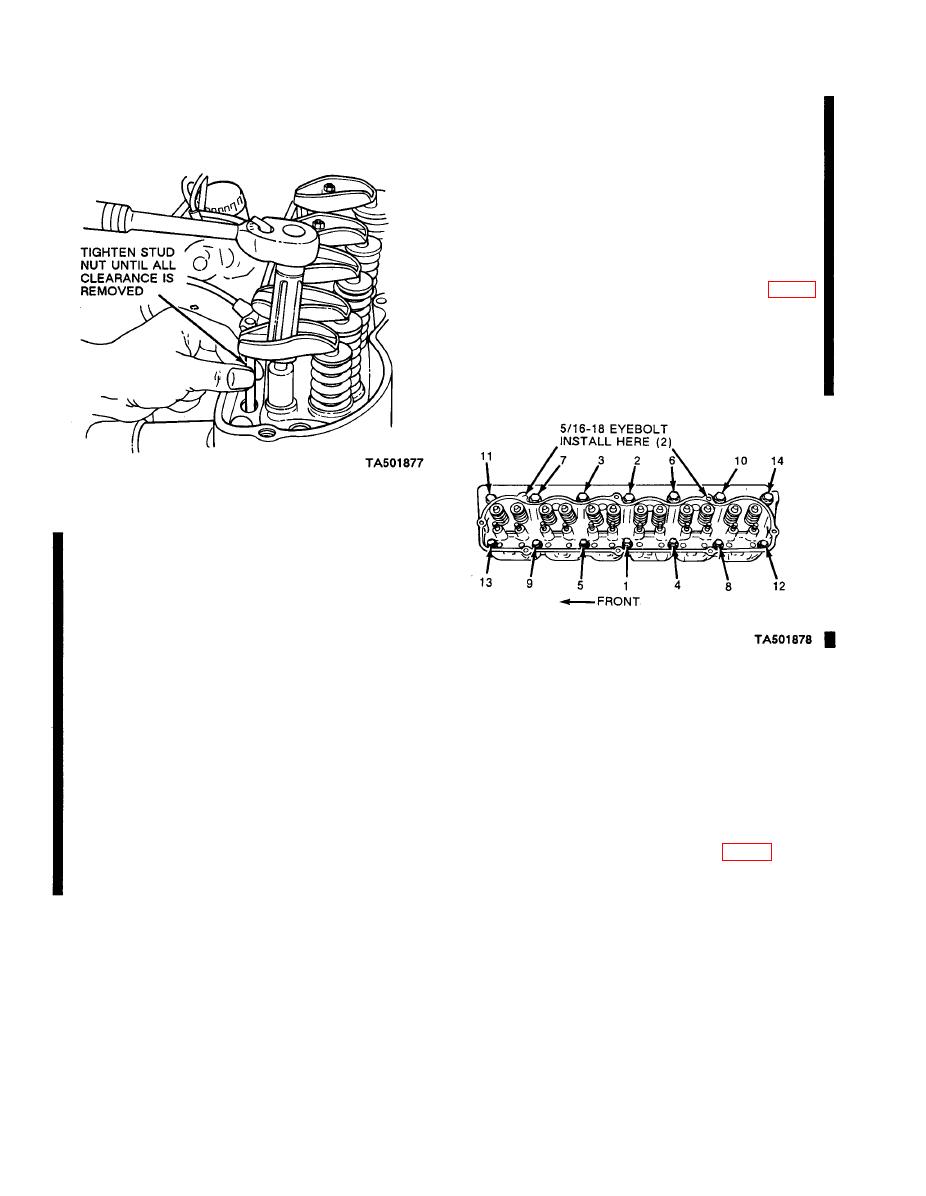
Figure 6-7.2. Valve Clearance Adjustment. |
|
||
| ||||||||||
|
|
 TM 10-3930-633-34
(9) Remove the coil bracket attaching bolt and
will cause a noisy lifter(s). If it has been determined
position the coil out of the way,
that these conditions are caused by improper valve
(10) Remove the valve rocker arm cover.
clearance, readjust the affected valve(s).
Loosen the rocker arm stud nuts so that the rocker
arms can be rotated to one side.
(11) Remove the valve push rods in sequence
and identify them so that they can be installed in their
original position.
(12) Disconnect the spark plug wires at the spark
plugs.
(13) Remove the cylinder head bolts. Install the
cylinder head lifting eyes in the locations shown in fig-
ure 6-7.3. Position a floor crane and attach the hoist
and lifting sling to the lifting eyes. Lift the cylinder
head and intake and exhaust manifolds assembly off
the engine. DO NOT PRY BETWEEN THE HEAD
AND BLOCK AS THE GASKET SURFACES MAY
BECOME DAMAGED.
6-14. Removal and Disassembly
If inspection or troubleshooting reveal cracked
cylinder head or defective gaskets, remove and
replace the cylinder head as follows:
a. Removal.
(1) Drain the cooling system.
(2) Remove the air cleaner ductwork.
(3) Remove the crankcase ventilation regulator
valve from the rocker arm cover. Disconnect the vent
hose at the intake manifold inlet tube,
b. Disassembly.
(4) Disconnect and remove the carburetor fuel
(1) Refer to TM 10-3930-633-12 and remove
inlet line and the distributor vacuum line.
the coolant outlet housing and thermostat, and the in-
(5) Disconnect the choke cable at the carbure-
tor and position the choke cable and housing out of
assembly.
the way.
(2) Remove the spark plugs.
(6) Remove the accelerator cable retracting
(3) Remove the deposits from the combustion
spring. Disconnect the accelerator cable from the car-
chambers and valve heads with a scraper and a wire
buretor.
brush before removing the valves. Be careful not to
scratch the cylinder head gasket surface,
(7) Disconnect the radiator upper hose at the
coolant outlet elbow.
(4) Compress the valve springs (fig. 6-8) then
remove the valve spring retainer locks and release the
(8) Disconnect the exhaust pipe from the ex-
spring.
haust manifold. Discard the inlet pipe gasket.
|
|
Privacy Statement - Press Release - Copyright Information. - Contact Us |
