 |
|||
|
|
|||
|
Page Title:
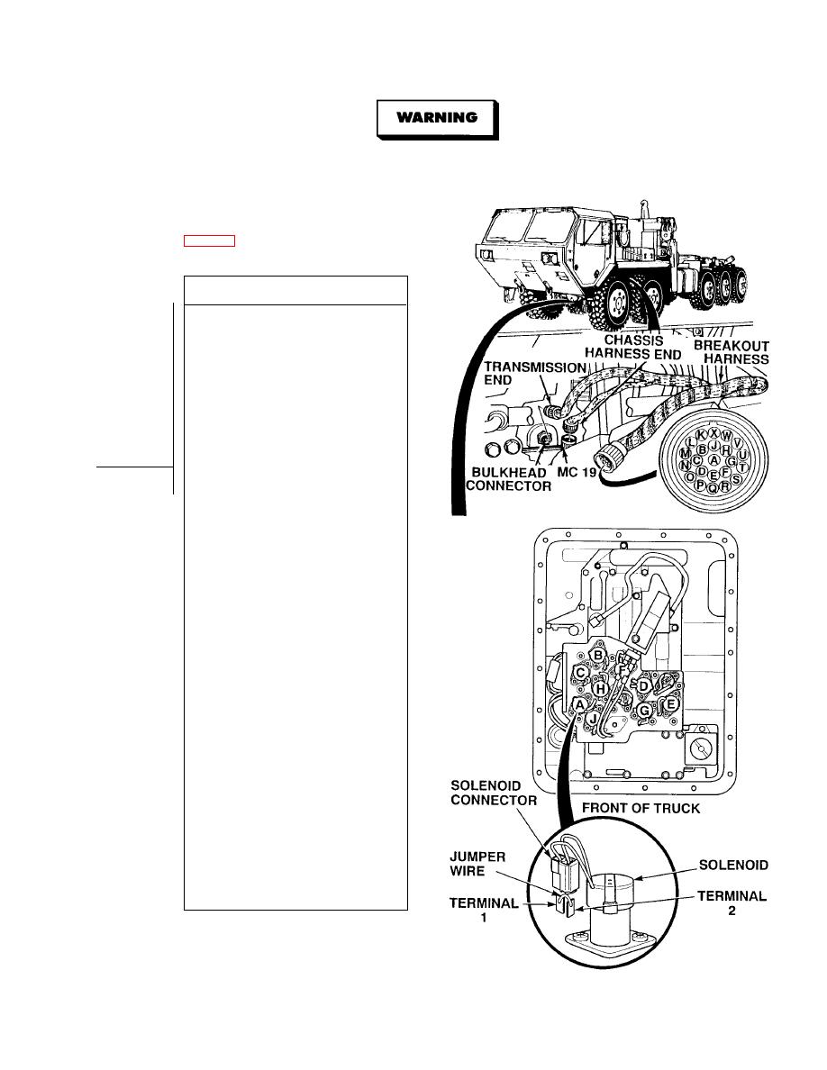
SOLENOIDS J, F, D, C, B, A, G, E OR H CIRCUIT FAULTY. (Cont) |
|
||
| ||||||||||
|
|
 TM 9-2320-364-34-1
Remove all jewelry such as rings, dog tags, bracelets, etc. If jewelry or tools contact positive electrical
circuits, a direct short may result. Damage to equipment, injury or death to personnel may occur.
NOTE
power input and output terminals for each solenoid.
CONTINUITY TEST
(1) Disconnect connector MC19 from
transmission bulkhead connector.
(2) Connect breakout harness connector
to transmission bulkhead connector.
(3) Is there continuity between the
breakout harness input terminal for
the suspected faulty solenoid, and
any other breakout harness terminal?
(a) If there is continuity, replace
solenoid wiring harness assembly
(Para 7-2).
(b) If there is no continuity, go to
Step (4) below.
(4) Is there continuity between the
breakout harness output terminal for
the suspected faulty solenoid, and
any other breakout harness terminal?
(a) If there is continuity, replace
solenoid wiring harness assembly
(Para 7-2).
(b) If there is no continuity, go to
Step (5) below.
(5) Connect a jumper wire between
terminals 1 and 2 of suspected faulty
solenoid.
(6) Is there continuity between the
breakout harness input and output
terminals of the suspected faulty
solenoid?
(a) If there is no continuity, replace
solenoid wiring harness assembly
(Para 7-2).
(b) If there is continuity, go to Step (7)
below.
(7) Is there continuity between terminal 1
and a known good ground with
jumper wire connected?
(a) If there is continuity, replace
solenoid wiring harness assembly
(Para 7-2).
(b) If there is no continuity, replace
ATEC ECU
(TM 9-2320-364-20).
(8) Remove jumper wire from terminals 1
and 2.
(9) Remove breakout harness.
(10) Connect connector MC19 to
transmission bulkhead connector.
(11) Install internal oil filter (Para 7-4).
|
|
Privacy Statement - Press Release - Copyright Information. - Contact Us |
