 |
|||
|
|
|||
|
Page Title:
Sxxx 0 - INJECTOR RESPONSE TIME LONG (cont) |
|
||
| ||||||||||
|
|
 TM 9-2320-364-20-1
Section IV. TROUBLESHOOTING CHARTS (Cont.)
E. FLASH CODE:
61
J1587 CODE:
Sxxx 0 - INJECTOR RESPONSE TIME LONG
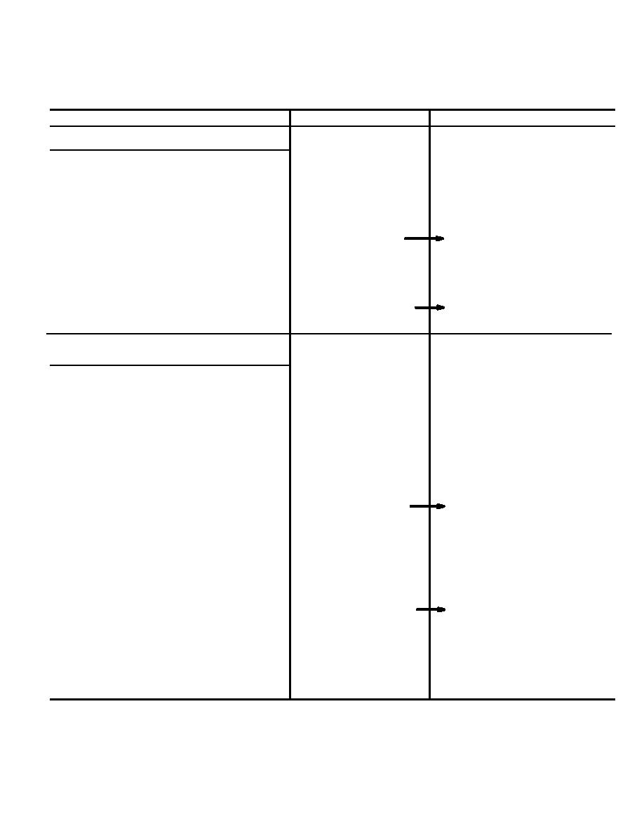
STEP/SEQUENCE
RESULT
WHAT TO DO NEXT
61-6
Resistance Test
Remove rocker arm cover (para
3-4 or 3-5) corresponding to
injector identified by Injector
Identification Table.
Disconnect two wires of the
injector indicated.
Measure resistance at the
More than or equal to
Go to 61-7.
injector harness connector
10,000 ohms or an open
terminals associated with the
circuit measured at
faulty injector.
injector harness
connector.
Less than 10,000 ohms
Repair wire or notify supervisor.
present.
Then go to 61-30.
61-7
Resistance Test
NOTE
Injector drive wires are numbered 611
through 618 and injector return wires
are numbered 619 and 620 on the
DDEC Injector Harness Wiring
Schematic (Fig 2-4).
Check for short to ground, working
with injector that has its two
wires disconnected.
Measure resistance between
More than or equal to
Go to 61--8.
injector drive wire and a known
10,000 ohms or an open
good ground.
circuit measured between
injector drive wire and
-- If there are less than 10,000 ohms
a known good ground.
present, repair wires tested (see
schematic Fig 2-4) or notify
DS Maintenance.
-- If there are more than 10,000 ohms
Less than 10,000 ohms
Repair drive wire and/or ground
present, perform the step below.
present.
or notify supervisor. Then go
to 61-30.
Measure resistance between one
of the terminals of the injector
(injector with disconnected wires)
and a known good ground.
2-735
|
|
Privacy Statement - Press Release - Copyright Information. - Contact Us |