 |
|||
|
|
|||
|
|
|||
| ||||||||||
|
|
 TM 9-2320-360-34-2
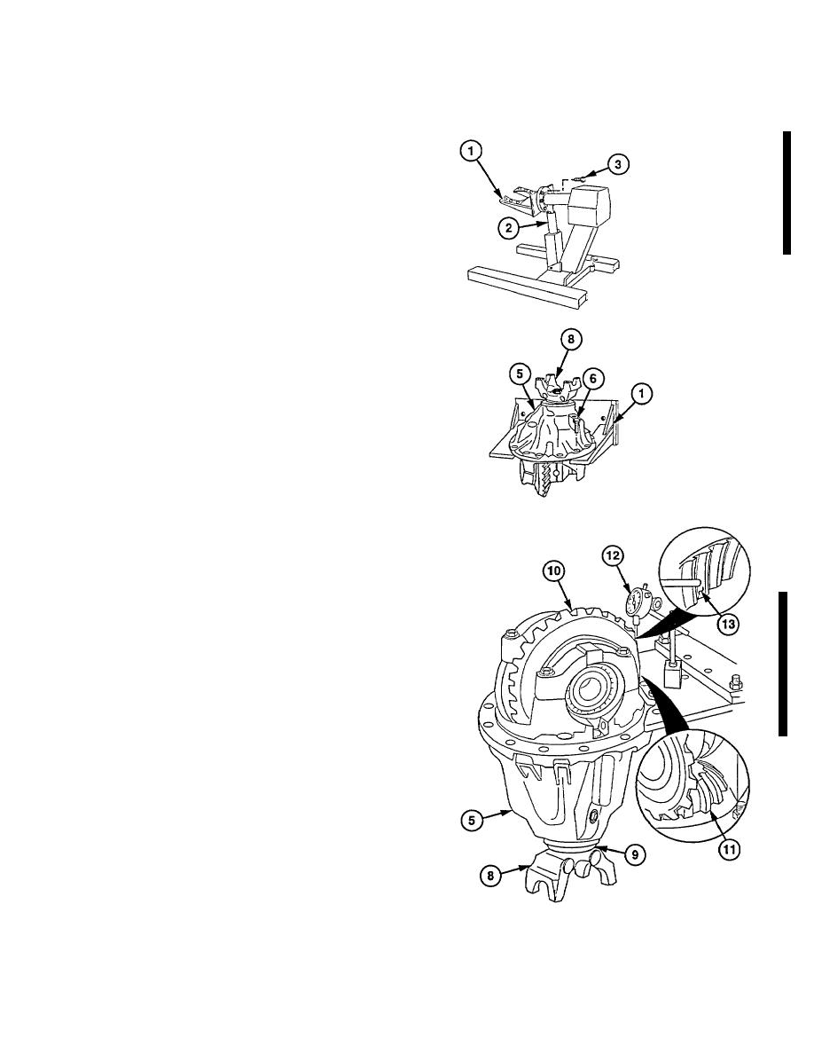
b. Disassembly
(1) Install adapter (1) on stand (2) with six
screws (3).
(2) Install differential assembly (5) on adapter
(1) with six screws (6).
(3) Remove lifting device from yoke (B).
(4) Position differential assembly (5) so pinion
shaft (9) points down.
(5) Check backlash of differential (10) to
pinion shaft (9).
(6) Hold yoke (8) so pinion gear (11) does not
move.
NOTE
Do not allow pinion gear to turn while
doing steps (7) thru (9).
(7) Turn differential (10) counterclockwise
until it stops to take up backlash.
NOTE
Shaft from dial indicator must be at
right (90) angle to face of tooth when
in contact.
(8) Install dial indicator (12) on face of
differential gear tooth (13).
(9) Turn differential (10) clockwise until it
stops.
NOTE
Backlash should be 0.008-0.011 in.
(0.003-0.004 mm).
To increase
backlash, reduce thickness of shims
installed in carrier housing.
To
decrease
backlash,
increase
thickness of shims.
(10) Record differential (10) to pinion shaft (9)
backlash measured on dial indicator (12).
Change 1 25-61
|
|
Privacy Statement - Press Release - Copyright Information. - Contact Us |
