 |
|||
|
|
|||
|
|
|||
| ||||||||||
|
|
 TM 9-2320-360-34-2
22-17. REAR COVER AND FIRST CLUTCH REPAIR (CONT)
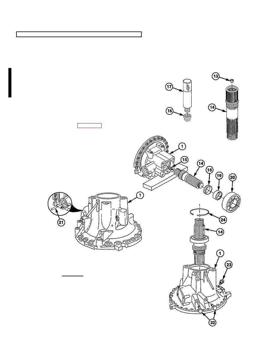
(11) Position rear cover (1) on side with
governor support pin access hole facing
down. Use wooden block for support.
(12) Install orifice plug (13) in output shaft (14).
CAUTION
A roller bearing must be pressed
back into a shaft that had a bearing,
and a bushing must be pressed back
into a shaft that had a bushing.
(13) Coat output shaft roller bearing (15) with
retaining compound.
(14) Install output shaft roller bearing (15) in
output shaft (14) using output shaft roller
bearing installer tool (16) and driver
handle (Item 66, Appendix E) (17).
(15) Install speedometer drive gear (18) and
spacer (19) on output shaft (14).
(16) Press bearing (20) on output shaft (14).
NOTE
Do step (17) only if governor support
pin was removed.
(17) Install governor support pin (21) in rear
cover (1) if removed.
(18) Coat threads of two small plugs (22) and
install in rear cover (1).
(19) Install large plug (23) in rear cover (1).
WARNING
Wear eye protection and use care
when installing retaining rings.
Retaining rings are under spring
tension and can act as projectiles
when released causing severe eye
injury.
(20) Install output shaft (14) and retaining ring
(24) in rear cover (1).
22-104 Change 2
|
|
Privacy Statement - Press Release - Copyright Information. - Contact Us |
