 |
|||
|
|
|||
|
|
|||
| ||||||||||
|
|
 TM 9-2320-360-34-2
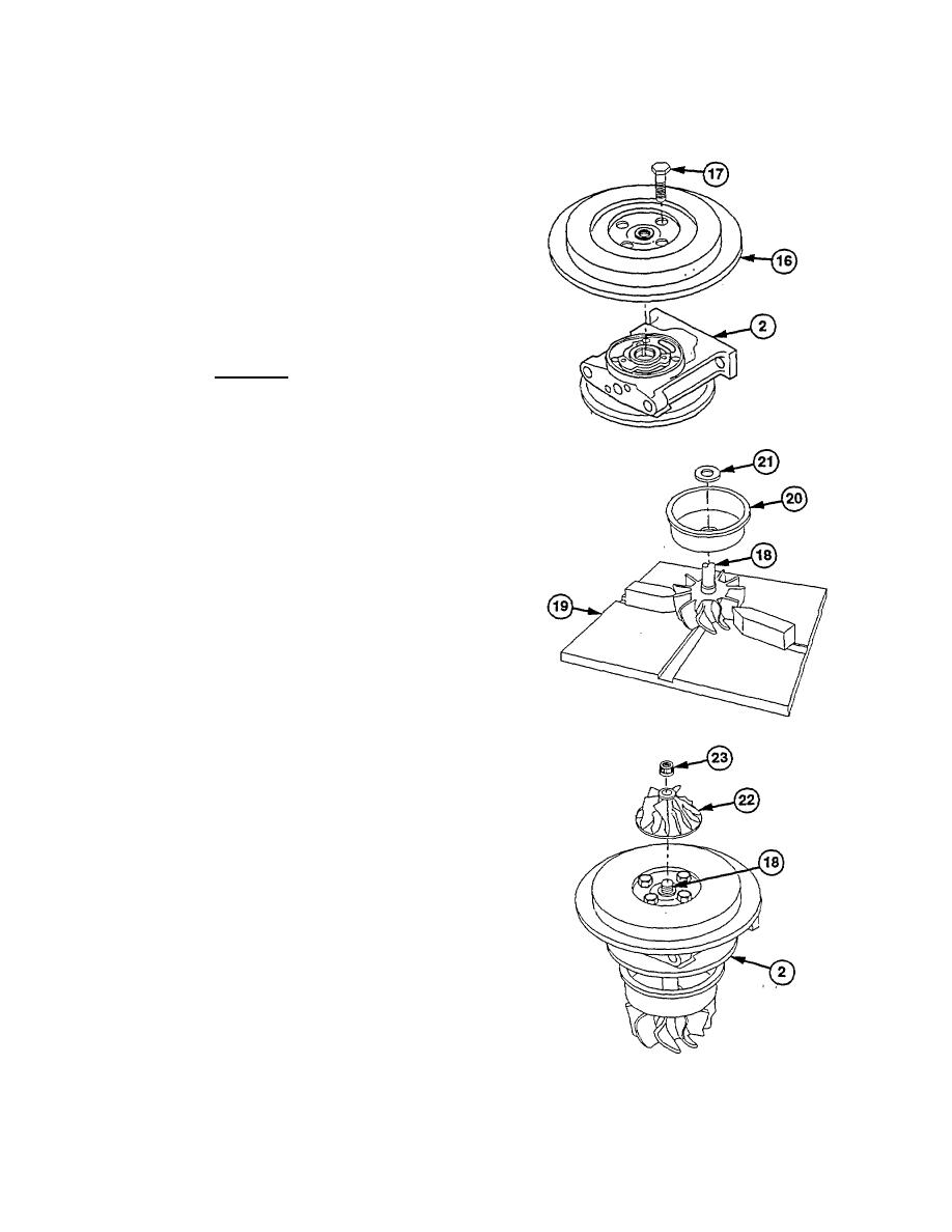
(9) Install backplate (16) on center housing (2),
aligning marks made during disassembly.
(10) Install four screws (17) in backplate (18).
Torque to 80-100 lb-in. (9.0-11.3 Nm).
(11) Position turbo wheel shaft (1 8) In holding fixture
(19).
(12) Install turbine wheel shroud (20) on turbo wheel
shaft (18).
WARNING
Wear eye protection and use care
when removing retaining rings.
Retaining rings are under spring
tension and can act as projectiles
when released causing severe eye
Injury.
(13) Coat lower piston ring groove with grease.
Install new retaining ring (21) in groove.
(14) Install center housing (2) on turbo wheel shaft
(18).
(15) Install impeller (22) on shaft (18).
(16) Position ne w locknut (23) on shaft (1B).
(17) Tighten locknut (23) to 135 lb-in. (14.9 Nm) with
aid of assistant.
(18) Remove locknut (23) from shaft (18) with aid of
assistant.
(19) Inspect locknut (23) and impeller (22) for
scratches. Ensure both contact surfaces are
clean and smooth. Replace damaged parts.
(20) Coat threads of shaft (18) and base of locknut
(23) with lubricating oil.
(21) Position locknut (23) on shaft (18). Torque to
35-55 lb-in. (4.0-6.2 N m) with aid of assistant.
Tighten 1/4 turn more.
20-23
|
|
Privacy Statement - Press Release - Copyright Information. - Contact Us |