|
| |
TM 9-2320-360-34-1
d.
Steering Gear Relief Adjustment.
NOTE
Do steps (1) thru (14) to adjust front
steering gear, steps (15) thru (28) to
adjust rear steering gear.
(1)
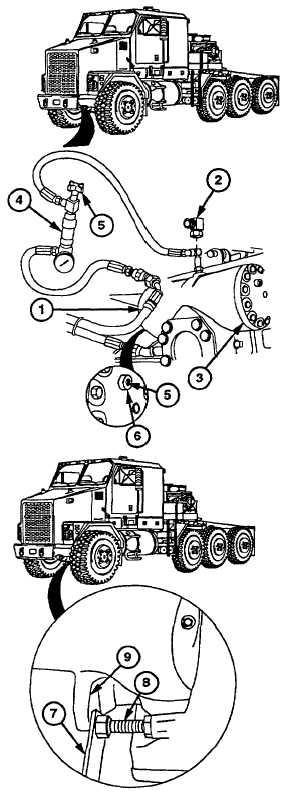
Remove hose no. 2301 (1) and elbow (2)
from front steering gear (3).
(2)
Install flowmeter (4) on hose no. 2301 (1)
and steering gear (3).
CAUTION
The relief valve plungers on front
steering gear must be adjusted so
there is 1/16 in. (1.6 mm) between
spindles and steering stops. A steel
plate must be held between steering
stop and axle housing to obtain this
space. Failure to comply may result
in damage to suspension, brake,
steering, or frame components.
NOTE
·
Turning relief plunger in will
increase
space
between
axle
stops; out will decrease space
between axle stops.
·
Leakage will occur if relief valve
plungers are turned beyond flush
with plunger boss.
(3)
Turn rear relief valve plunger (5) out until
flush with plunger boss (6).
(4)
Start engine (TM 9-2320-360-10).
WARNING
Keep
hands
and
fingers
from
between steering stop and axle
housing. Failure to comply will result
In injury to personnel.
(5)
Place steel plate (7) between steering
stop bolt (8) and axle housing (9) while
assistant holds steering wheel in full right
position.
(6)
Turn rear relief plunger (5) in until
pressure gage reads 500-650 psi (3448-
4482 kPa).
Change 1 13-63
|