|
| |
TM 9-2320-360-34-1
13-9. STEERING STOP BOLT REPLACEMENT/ADJUSTMENT
This task covers:
Removal
Adjustment
Installation
Follow-On Maintenance
INITIAL SETUP
Equipment Conditions
Tools and Special Tools
Steering system adjusted (para 13-8).
Tool Kit, Genl Mech (Item 202, Appendix E)
CTIS in highway mode (TM 9-2320-360-10).
Hydraulic Test Kit (Item 72, Appendix E)
Tires inflated to 75 psi (517 kPa).
Jack, Floor (Item 90, Appendix E)
Engine shut off (TM 9-2320-360-10).
Jackstands (5) (Item 93, Appendix E)
Parking brake on (TM 9-2320-360-10).
Plate, Steel (Figure C-13, Appendix C)
Wheels straight ahead.
Template, Steering Radius (Figure C-22,
Appendix C)
Personnel Required
Tape, Measuring, 12 Ft (Item 189, Appendix E)
Two
Wrench, Torque, 0-175 Lb-Ft (Item 236
Appendix E)
Plumb Bob (Item 115.1, Appendix E)
NOTE
Both front and rear axle stops are
removed the same way. Axle no. 1 is
shown.
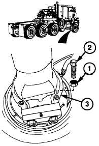
a.
Removal
(1)
Loosen jam nut (1) on steering stop bolt
(2).
(2)
Remove steering stop bolt (2) and jam nut
(1) from spindle (3).
b.
Installation.
(1)
Install steering stop bolt (2) and jam nut
(1) on spindle (3).
(2)
Tighten jam nut (1) on steering stop bolt
(2).
c.
Adjustment
(1)
Start engine (TM 9-2320-360-10).
(2)
Drive HET Tractor straight back about 20
ft (6 m), then straight forward about 20 ft
(6 m). Park with wheels straight.
(3)
Shut off engine (TM 9-2320-360-10).
(4)
Chock wheels (axle no. 2 or axle no. 3).
(5)
Deleted.
13-56 Change 3
|