|
| |
TM 9-2320-360-34-1
13-8. STEERING SYSTEM ADJUSTMENT (CONT)
CAUTION
Drag link must drop directly into hole
in steering arm. If steering arm or
pitman arm is moved when installing
drag link, HET Tractor alignment will
be incorrect and dogtracking or tire
wear may result.
NOTE
·
If drag link does not drop directly
into steering arm, do steps (9)
and (10).
·
Axle no. 1 and axle no. 4 drag
links are positioned in the same
manner. Axle no. 4 is shown.
·
Initial distance between drag link
grease fittings is 40 in. (101.6 cm)
for axle no. 1 and 34 in. (86.4 cm)
for axle no. 4.
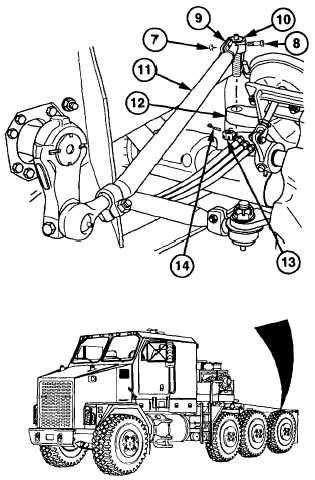
(9)
Remove locknut (7) and screw (8) from
drag link clamp (9). Discard locknut.
(10)
Rotate drag link end (10) clockwise to
shorten and counterclockwise to lengthen
drag link (11).
(11)
Install drag link (11) on steering arm (12).
CAUTION
The front clamp on the axle no. 1
drag link must be positioned so the
clamp screw is vertical. Failure to
comply
may
result
in
screw
contacting
the
frame,
causing
damage to equipment.
NOTE
Go to step (13) if drag link was not
adjusted.
(12)
Tighten drag link clamp (9) with screw (8)
and new locknut (7). Torque to 70 lb-ft
(95 Nm).
(13)
Repeat steps (1) thru (6) to verify
adjustment.
(14)
Install nut (13) on drag link (11). Torque
to 165 lb-ft (224 Nm).
(15)
Continue tightening until hole in drag link
end (10) aligns with slots in nut (13).
(16)
Install new cotter pin (14) through nut (13)
and drag link end (10).
(17)
Repeat steps (9) thru (16) for axle no. 1.
13-48 (13-49 thru 13-54 deleted) Change 2
|