|
| |
TM 9-2320-360-34-1
WARNING
Exhaust manifolds and engine parts are
hot. Use care to prevent personal injury.
Table 2-9. Injector Harness Connector Identification
INJECTOR
INJECTOR
HARNESS
HARNESS
CONNECTOR
CONNECTOR
SID
SOCKET
SOCKET
S001
A
F
S002
K
G
S003
B
E
S004
H
G
S005
D
E
S006
J
G
S007
C
E
S008
L
G
CONTINUITY TEST
(1) Turn ENGINE switch OFF and unplug DDR.
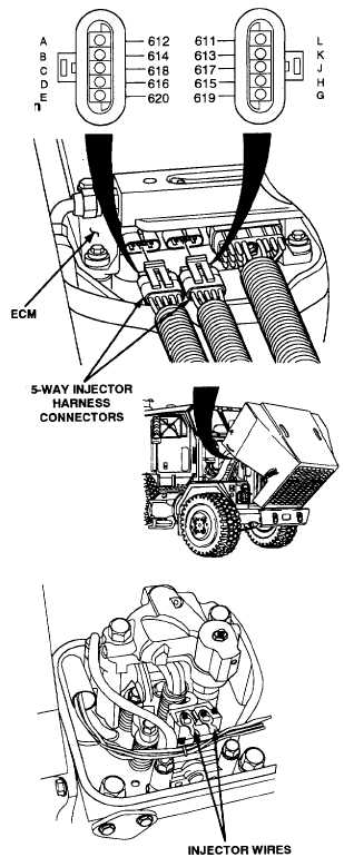
(2) Disconnect both 5-way injector harness
connectors at the ECM.
(3) Referring to Table 2-9, read resistance
between the 5-way injector harness connector
sockets associated with the SID received.
(Example: read resistance between sockets G
and A for SID S001.)
CONTINUITY TEST
(1) Remove rocker arm cover
(TM 9-2320-360-20) corresponding to injector
identified by Table 2-8.
(2) Disconnect the two wires of the injector
identified. Short these two wires together.
(3) Referring to Table 2-9, read the resistance
between the 5-way injector harness connector
sockets associated with the faulty injector.
CONTINUITY TEST
(1) Remove rocker arm cover
(TM 9-2320-360-20) corresponding
to injector identified by Table 2-8.
(2) Disconnect two wires of injector indicated.
(3) Referring to Table 2-9, read the resistance
between 5-way injector harness connector
sockets associated with faulty injector.
Change 3 2-62.3
|

