|
| |
TM 9-2320-360-34-1
11-3. AXLE NO. 1 AND AXLE NO. 4 BRAKE BRACKET/CAMSHAFT REPAIR
This task covers
a. Removal
d. Assembly
b. Disassembly
e. Installation
c. Cleaning/Inspection
f. Follow-On Maintenance
INITIAL SETUP
Equipment Conditions
Tools and Special Tools (Cont)
Brake shoes removed (TM 9-2320-360-20).
Wrench, Torque, 0-600 Ft-Lb (Item 233,
Slack adjuster removed (TM 9-2320-360-20).
Appendix E)
Wheel hub removed (para 12-3).
Materials/Parts
Tools and Special Tools
Adhesive-Sealant (Item 6, Appendix B)
Tool Kit, Genl Mech (Item 202, Appendix E)
Oil, Lubricating (Item 46, Appendix B)
Goggles, Industrial (Item 57, Appendix E)
Seals (2) (Item 287, Appendix F)
Pliers, Retaining Ring (Item 108, Appendix E)
Seals (2) (Item 289, Appendix F)
Socket, Sockethead Screw, 14 mm (Item 173,
Appendix E)
a.
Removal
WARNING
· Left and right camshafts are
different and not interchangeable.
Using wrong camshaft may result
in inoperative brakes and injury to
personnel.
· Wear eye protection and use care
when removing retaining rings.
Retaining rings are under spring
tension and can act as projectiles
when released causing severe eye
injury.
NOTE
Axle no. 1 and axle no. 4 camshafts
are replaced the same way. Axle no.
1 is shown.
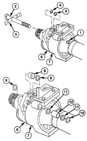
(1)
Remove retaining ring (1) from camshaft
(2).
(2)
Remove retaining ring (3), washer (4), and
thrust washer (5) from brake bracket (6)
and spindle assembly (7) while pulling
camshaft (2).
(3)
Remove two seals (8) and bushing (9)
from brake bracket (6). Discard seals.
(4)
Remove spacer (10), two seals (11), and
bushing (12) from spindle assembly (7).
Discard seals.
11-4
|