|
| |
TM 9-2320-360-34-1
(11)
Calculate shim height and install as
follows:
(a)
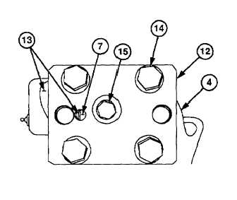
Install king pin preload cover (12) on
upper pivot face (13) with four
screws (14). Torque to 200 lb-ft
(271 Nm).
(b)
Install central screw (15) on tool
(12). Torque to 200 lb-ft (271 Nm).
(c)
Loosen screw (15) slightly until pivot
and spindle assembly (4) moves
freely.
NOTE
Measurement in step (11)(d) must be
made from either of the two screws
closest to the spindle.
(d)
Verify pivot and spindle assembly
(4) requires no more than 57 lb-ft
(77 Nm) to start rotation from
centered position.
(e)
Measure distance between top of
link pin (7) and upper pivot face (13)
using depth micrometer gage.
NOTE
Refer
to
table
9-1
for
shim
requirement.
(f)
Remove four screws (14) and king
pin preload cover (12) from upper
pivot face (13).
Table 9-1. Determining Shim Thickness
Distance Between Pivot and Spindle
Assembly and Link Pin
Shim Thickness
0.018 to 0.022 in. (0.45 to 0.55 mm)
0.016 in. (0.4 mm)
0.022 to 0.026 in. (0.55 to 0.65 mm)
0.020 in. (0.5 mm)
0.026 to 0.030 in. (0.65 to 0.75 mm)
0.024 in. (0.6 mm)
0.030 to 0.033 in. (0.75 to 0.85 mm)
0.028 in. (0.7 mm)
0.033 to 0.037 in. (0.85 to 0.95 mm)
0.031 in. (0.8 mm)
0.037 to 0.041 in. (0.95 to 1.05 mm)
0.035 in. (0.9 mm)
0.041 to 0.045 in. (1.05 to 1.15 mm)
0.039 in. (1.0 mm)
9-21
|