|
| |
TM 9-2320-360-34-1
8-3. TRANSFER CASE REPLACEMENT
This task covers:
a. Removal
c.
Follow-On Maintenance
b. Installation
INITIAL SETUP
Equipment Conditions
Materials/Parts
Transfer case in LOW range
Adhesive-Sealant (Item 3, Appendix B)
(TM 9-2320-360-10).
Adhesive-Sealant (Item 5, Appendix B)
Transfer case input shaft removed
Adhesive-Sealant (Item 6, Appendix B)
(TM 9-2320-360-20).
Grease, Anticorrosion (Item 31, Appendix B)
Front axle propshaft removed
Ties, Cable, Plastic (Item 60, Appendix B)
(TM 9-2320-360-20).
Fasteners, Ratchet (7) (Item 11, Appendix F)
No. 2 axle input propshaft removed
Locknuts (4) (Item 87, Appendix F)
(TM 9-2320-360-20).
Lockwashers (2) (Item 119, Appendix F)
No. 5 air reservoir removed
Lockwasher (Item 117, Appendix F)
(TM 9-2320-360-20).
Pin, Cotter (Item 218. Appendix F)
Transfer case drained (LO 9-2320-360-12).
Personnel Required
Tools and Special Tools
Two
Tool Kit, Genl Mech (Item 202, Appendix E)
Jack, Floor (Dolly Type), 10-Ton
Special Environmental Conditions
(Item 90, Appendix E)
HET Tractor parked on hard, level surface.
Lift, Transmission and Differential
(Item 95, Appendix E)
Jackstands, 7-Ton (2) (Item 93, Appendix E)
Wrench Set, Socket, 3/4 In. Drive (Item 231,
Appendix E)
Wrench, Torque, 0-600 Lb-Ft (Item 233,
Appendix E)
a.
Removal
WARNING
Do not work on any item supported
only by jacks or hoist. Always use
blocks or proper stands to support
the
item
prior
to
any
work.
Equipment may fall and cause injury
or death to personnel.
NOTE
There must be 42 in. (104 cm)
between bottom of right frame rail
and ground to remove transfer case.
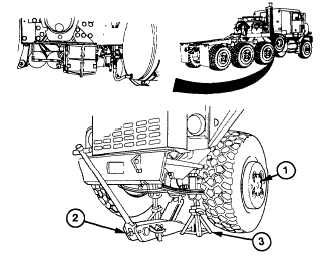
(1)
Raise axle no. 1 with floor jack (2) and
support axle (1) with two jackstands (3).
Change 3 8-5
|