|
| |
TM 9-2320-360-34-1
6-4. STARTER REPAIR (CONT)
c.
Testing
(1)
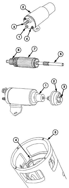
Connect one multimeter test lead to
terminal no. 1 (1) and second test lead to
a bare metal surface on switch housing
(2). Ohmeter should read no continuity
(infinity). Low resistance indicates coil is
grounded and switch assembly must be
replaced.
(2)
Connect one multimeter test lead to
terminal no. 3 (3) and second test lead to
terminal no. 4 (4). If readings fall outside
0-5 ohms, switch must be replaced.
(3)
Connect one multimeter test lead to
splined end of armature shaft (5). Run
second test lead across all commutator (6)
contacts. Ohmeter should read no
continuity
(infinity).
Low
resistance
indicates a ground and armature (7) must
be replaced.
d.
Assembly
CAUTION
Plunger
must
be
wrapped
with
crocus cloth to protect plunger when
installing link spool in step
(2)
Failure to comply may result in kinks on
plunger and damage to equipment.
(1)
Wrap strip of crocus cloth twice around
plunger (1).
(2)
Install rubber boot (2) and link spool (3) on
plunger (1) using adjustable joint pliers to
hold plunger (1).
NOTE
Paper
insulator
is
positioned
between field ring and field coil
jumper.
(3)
Install paper insulator (4) in field ring (5).
6-36
|