|
| |
TM 9-2320-360-34-1
NOTE
If
using
original
brushes,
wear
pattern must match radius of slip
rings.
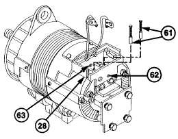
(28)
Insert two brushes (61) into regulator
holder (28).
NOTE
Brush springs are held compressed
with 1/16 in. sockethead screw key
to
aid
installation
of
voltage
regulator.
(29)
Compress brush springs (61). Install 1/16
in. sockethead screw key through pilot
hole (62) in regulator holder (28), over
springs (61), and into pilot hole (63) inside
regulator holder (28).
CAUTION
Regulator can only be installed one way. Position regulator so regulator pins align
with brush openings. Failure to comply may result in damage to equipment.
NOTE
Regulator must be positioned close to housing to allow installation of wires.
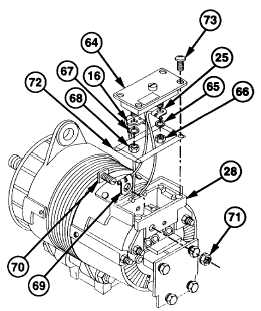
(30)
Install red wire (25) on positive (+)
terminal of voltage regulator (64) with new
lockwasher (65) and nut (66).
(31)
Install black wire (16) on negative (-)
terminal of voltage regulator (64) with new
lockwasher (67) and nut (68).
(32)
Install blue wire (69) and ignition ( IGN)
stud (70) in regulator holder (28).
(33)
Install tenz nut (71) on ignition (IGN) stud
(70).
CAUTION
Brush
retaining
pin
must
be
positioned
in
grooves
between
regulator holder and slip ring end
housing. Failure to comply may
result in damaged wiring.
(34)
Position new gasket (72) and voltage
regulator (64) on regulator holder (28) with
four screws (73). Do not tighten.
(35)
Remove sockethead screw key from rear
of regulator holder (28).
(36)
Tighten four screws (73) on voltage
regulator (64).
e.
Follow-On Maintenance
Install alternator (TM 9-2320-360-20).
6-29
|