|
| |
TM 9-2320-360-34-1
6-3. 24-VOLT ALTERNATOR REPAIR (CONT)
(14)
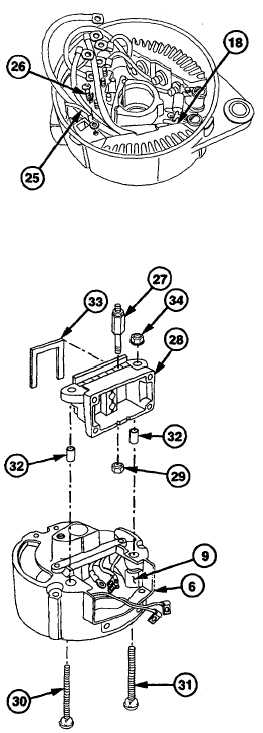
Install red wire (25) on positive (+) rectifier
(18) with screw (26).
(15)
Install
three
terminal
studs
(27)
on
regulator holder (28) with three nuts (29).
CAUTION
Red and black rectifier wires should
be positioned in grooves between
regulator holder and slip ring end
housing. Failure to comply may
result in damaged wiring.
(16)
Install positive (+) terminal screw (30),
negative (-) terminal screw (31), two
insulation bushings (32), regulator holder
(28), new gasket (33), and two tenz nuts
(34) in slip ring end housing (6), positive
(+) rectifier (18), and negative (-) rectifier
(9).
NOTE
· Rectifier leads should be firmly
seated in regulator holder.
· Wires should be positioned in
locations marked during removal.
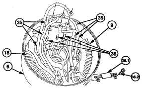
(17)
Install six rectifier leads (35) on three
regulator studs (36).
(17.1)
Install capacitor (36.1) on positive rectifier
(18) and negative rectifier (9) with two
screws (36.2).
6-26 Change 1
|