|
| |
TM 9-2320-360-34-1
5-5. WATER PUMP REPLACEMENT (CONT)
(9)
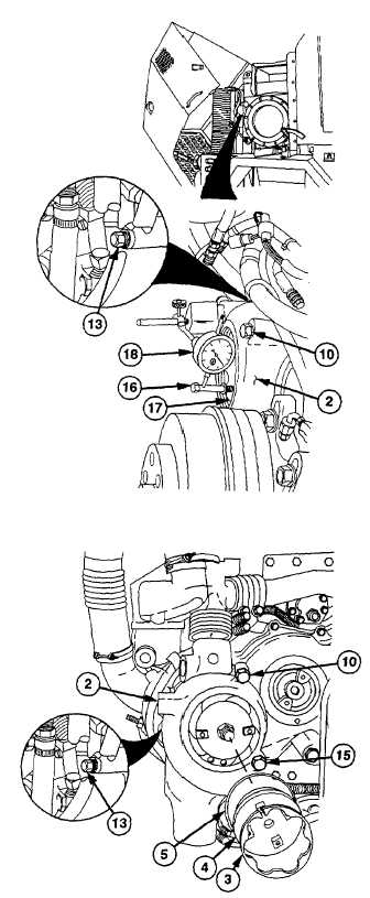
Install 5/16-18 x 2 in. screw (16) into
impeller (17).
NOTE
Limits for gear backlash are 0.001 in.
to 0.006 in. (0.025 mm to 0.15 mm). If
backlash cannot be adjusted, replace
pump.
(10)
Place plunger of dial indicator (18) against
screw (16). Move impeller (17) and read
backlash.
NOTE
If backlash is outside limits, do steps
(11) and (12).
(11)
Loosen two screws (10 and 13) and pivot
water pump (2) to obtain proper backlash.
(12)
Tighten screws (10 and 13) to 30 lb-ft (34
Nm).
(13)
Remove screw (16) from water pump (2).
(14)
Tighten screws (10, 13, and 15) to 45 to
50 lb-ft (61 to 67 Nm).
·
Wear eye protection and use care
when installing retaining rings.
Retaining rings are under spring
tension and can act as projectiles
when released and may cause
severe eye injury.
·
Due to size and tension of
retaining ring in step (15), ensure
suitable retaining ring pliers are
used for safety. Press a hammer
against the access cover to help
prevent
injury
should
the
retaining ring slip off the pliers.
(15)
Install new seal ring (5), access cover (4),
and new retaining ring (3) on water pump
(2).
5-22
|