Order this information in Print

Order this information on CD-ROM

Download in PDF Format


Click here to make tpub.com your Home Page

Page Title: Removal
Back | Up | Next

Click here for a printed version

Google


Web
www.tpub.com

Home


Information Categories
.... Administration
Advancement
Aerographer
Automotive
Aviation
Combat
Construction
Diving
Draftsman
Engineering
Electronics
Food and Cooking
Math
Medical
Music
Nuclear Fundamentals
Photography
Religion
USMC
   
Products
  Educational CD-ROM's
Printed Manuals
Downloadable Books


TM 9-2320-360-34-1 NOTE 
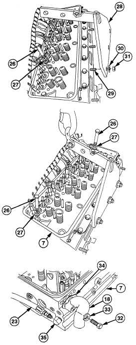
Leave   upper   left   and   right   screws installed until step (16). (13) Remove   eight   screws   (26)   and   washers (27). (14) Install  lifting  fixture  (28)  over  three  studs (29)   with   three   washers   (30)   and   nuts (31). (15) Install   suitable   lifting   device   to   support weight of cylinder head (7). (16) Remove   two   screws   (26)   and   washers (27). CAUTION After cylinder head is removed, cover camshaft   pockets   to   prevent   debris from    entering    engine.        Failure    to comply    may    result    in    damage    to valve train. (17) Using  lifting  device,  remove  cylinder  head (7) and place on wooden blocks. NOTE Do steps (18) and (19) for left cylinder head only. (18) Remove    two    screws    (32),    lockwashers (33),  breather  tube  (18),  and  gasket  (34) from   cylinder   head   (7).      Discard   gasket and lockwashers. (19) Remove  fuel  line  (23)  from  fitting  (35)  on cylinder head (7). 3-75

Privacy Statement - Press Release - Copyright Information. - Contact Us - Support Integrated Publishing

Integrated Publishing, Inc. - A (SDVOSB) Service Disabled Veteran Owned Small Business