|
| |
TM9-2320-360-20-3
Section 2
BASIC KNOWLEDGE REQUIRED (Cont’d)
3. Put one test probe at one end of the wire or circuit to be tested. Use the other test lead to trace the circuit. When
continuity is established, an W symbol will appear in the upper left corner of the digital display. If contact in the wire is
maintained long enough (about 1/4 of a second), the OL will disappear and the resistance value of the wire or circuit
will appear next to the symbol.
4. If your VOM does not work in the manner described above, you must know how your VOM operates in order to use this
troubleshooting guide.
Voltage Measurements
1. Connect the red test lead to the V - W input connector and the black lead to the com input on the meter. If a DC-AC
switch is present, make sure it is switched to the DC position.
2. Set the function range switch to the desired volts position. If the magnitude of the voltage is not known, set the switch to
a range which will be able to read most voltages seen on a vehicle. (Typical, a 20V range will do.) Then reduce the
range until a satisfactory reading is obtained.
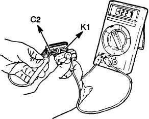
3. Connect the test leads to the circuit being measured. In the DDEC III diagnostic procedures, voltage measurements
are always given as being taken at pins, sockets, Battery +, or ground. Following the voltage measurement point, the
color test lead to be used is given in parenthesis (red is the V - W connection, an black is the corn connection). Example:
If the procedure says, “Take voltage reading at socket C2 (red lead) to socket K1 (black lead)“, the hook-up would be
as follows:
C. IMPORTANT INFORMATION
The following items must be read and thoroughly understood before using this manual.
1. The engine and ignition should always be off before the harness connectors are disconnected or reconnected.
2. When disconnecting harness connectors, be sure that the pulling force is applied to the connectors themselves and
not the wires extending from them.
3. After harness connectors are reconnected to the DDEC III system, the codes logged should be ignored and cleared.
4. In most all areas of Repair/Troubleshooting, a diagnostic data reader will be required.
H-4
|